PA0SE
pg 10a INTRO to German WW2 Radio equipment
(Radio Bygones No65, June/July 2000)
German World War II Radio
Equipment
By Dick Rollema PA0SE
This article is based upon two papers: 'Some Aspects of
Unconventional Engineering during Interbellum - as particularly
in Germany to enhance the specifications of their communication
apparatus' and 'Receiver and transmitter development in Germany
1920-1945', both written by Arthur O. Bauer, PA0AOB, president of
the Foundation Centre for German Communication and related
Technology 1920-1945. The B/W photographs were taken at Arthur's
beautiful collection. His help is gratefully acknowledged (The
colour pictures are taken by LA8AK).
HOW IT BEGAN
Development of radio equipment in Germany at first went
along the same lines as in other countries. Components were
mounted on wooden baseboards and behind a front panel of Bakelite
or similar material. More expensive sets featured a cabinet, also
made of wood. Electrical shielding was hardly used and coils were
of the open ('air cored') type. For a reasonable Q coils had to
be of large size and were sometimes wound with 'litz wire', made
of a bundle of individually insulated strands. Also special
winding techniques were employed to reduce self-capacitance of
the coils.
By the end of the twenties a different approach was initiated in
Germany. There were several important developments that made this
possible.
NEW CERAMICS
Ceramic insulation had already been used for many years
but only for DC and low frequency AC.
For frequencies above 1 MHz dielectric losses in the material
were too high. This was
changed in the second half of the 1920s when German firm
Hermsdorf-Schomburg-Isolatoren-Gesellschaft,
also known as Hescho, marketed new types of ceramic material with
very low loss at RF, due to the absence of iron.
At first Hescho had problems in measuring the loss. But the
solution came from young physicists Dr Rohde and
Dr Schwarz who developed suitable test equipment. That was the
start of their successful firm
'Physikalisch-technisches Entwicklungslabor Dr Rohde
& Dr Schwarz'.
After the war well known as 'Rohde & Schwarz' (R&S).
Their first export order
came from Britain in 1934 for a 'tan delta measuring
device'.
After 1933/1934 low loss titanium dioxide capacitors with
controlled temperature constant became available and these were
especially suitable for frequency stabilisation of free-running
oscillators, as will be seen later.
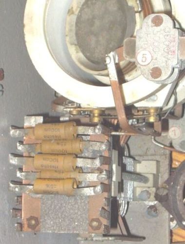
Temperature stabilization block of capacitors
(EZ6) is shown on uppper left side of the picture)
 |
 |
Lo40K39a and Lo40K39d temperature compensations
are somewhat different.
Ceramics also made possible very good coils, manufactured by
vaporising and burning a heavy copper and/or silver layer onto a
ceramic cylinder. Parts of the layer were then cut away such that
a helix remained, forming the coil winding.
Stable coils with high Q could thus be mass-produced. The
construction also resulted in a very low temperature coefficient,
equal to that of the ceramic material and not of the metal of the
winding. Siemens reported temperature coefficient of such coils
was up to 200 times lower than that of the best conventionally
made coils.
Ceramics also made possible very good coils, manufactured by
vaporising and burning
copper and/or silver layer onto a ceramic cylinder. Parts of the
layer were then cut away
such that a heliz remained.
IRON DUST CORES
Coils with iron dust cores were already used by the
telephone industry in the early 1920s, for instance as Pupin line
loading coils, but they were not suitable for frequencies above
about 10 kHz.
A great improvement was made by versatile inventor Hans Vogt who
had the smart idea of using 'carbonyl iron'. The advantage of
this material was that the iron dust particles were spherical and
only between 2 and 6 micron in diameter, with a very thin oxide
film on their surface. This avoided eddy currents and the
associated losses. In the thirties the material became known in
Britain and Germany by its trade name 'Ferrocart'.
It made possible compact coils of high quality that could be
easily screened by a small can without affecting their Q.
DIE-CAST FRAMES
After the radio on a wooden baseboard the use of a metal
chassis became popular, and it remained like that till the
appearance of the printed circuit board.
Early in the 1930s C. Lorenz company (since May 1930 owned by
ITT, after WWII known as Standard Elektric Lorenz until the end
of the 1980s; now owned by French Alcatel) was looking for more
rational construction techniques. Until then the chassis moved
all the way from the metal workshop up to the testing station at
the end of the production line. So only a few people could work
on it at the same time. Lorenz wanted a construction consisting
of separate modules which in the final stage of the production
line could be bolted or clicked together. Such modules could be
manufactured at the most suitable production site, even being
tested and calibrated there.
The use of die-casting (Spritzguss) was soon found to be the
answer. For their application, involving small and relatively
complicated shapes and very tight tolerances, Lorenz sought
support from outside. That was found at the firm of Mahle,
manufacturer of aluminium pistons for internal combustion
engines. According to an advertisement in a German technical
magazine of 1938, Mahle could produce die-cast samples of
0.5-2000 gram and tolerances of a few hundredths of a millimetre!
The alloy used became known as 'Elektron' and consisted of about
8.5-9.5% Al; 0.5% Zn; 0.2% Si; 0.2% Mn and the rest Mg. It had a
specific gravity of only 1.8.
During the war, shortage of aluminium forced the industry to
replace the lightweight Elektron by an alloy based on zinc. After
mid 1943 the German Army received more and more equipment made of
the much heavier zinc alloy. Only the Luftwaffe (Air Force), the
best equipped of the three forces, retained the high quality
Elektron for their radios.
LIMITED NUMBER OF VALVES
The German air force, army and navy were trying to
standardise their components as much as possible. A problem was
the large number of different valves used in communications
equipment. It was therefore decided to force the industry to
integrate and co-ordinate their activities on commercial and
military projects. This resulted in a completely new generation
of radio receiver and transmitter valves. Also the number of
different types was greatly reduced. Several military receivers
used only one type of valve in all stages. This was the universal
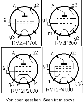
pentode RV12P2000 (Photo 1). R stood for valve (Rohre); V = low
power, 12 = heater voltage; P = pentode, 2000 = amplification
factor (mu). More than 16 million were produced during WWII. The
valve is inserted upside down into its holder, which completely
surrounds it. To withdraw the valve a knob, visible on Photo 1,
is screwed into the bottom.
In the later to be described aircraft radio FUG 10, as well as in
many other transmitters, pentode RL12P35 with 35 watt anode
dissipation was used. Details of this valve can be found in 'The
German 807s? The RL12P35 and its derivatives' by Alan Davies,
RB49, October/November 1997.
The author still uses three of these valves in parallel in the
final amplifier of his home-made amateur single sideband
transmitter, built in 1967. Though in frequent use, over all
those years only two of them had to be replaced, in one case the
cause being an open contact at the antenna connector, resulting
in severe overloading of the valves. The RL12P35 was designed in
1935 and never meant for linear amplification but the valve
nevertheless performs very well in this mode. Between them the
three develop some 130W peak envelope power with very low
distortion. The author presently is constructing a new
transceiver for the amateur bands 10-160 metres. This will be
transistorised except for the final amplifier which again has
three RL12P35's in parallel!
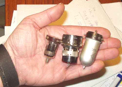
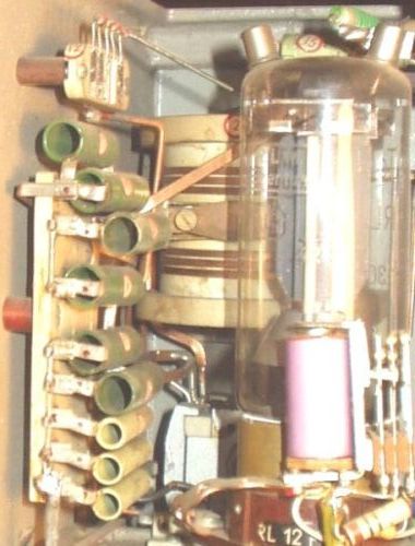
Universal pentode RV12P2000 (RV2,4P700), socket, and the special
type "AF100"
AIRCRAFT RADIO EQUIPMENT FuG X (= FuG 10)
In August 1936 the Reichsluftfahrtministerium (German Air
Ministry) issued new specifications for radio equipment to be
used on board aircraft. It had to cover long wave, short wave and
even VHF in the future. It was to be standard equipment for more
than a decade. The specifications were very tight: Frequency
should stay within 3 x l0 E-4 of the set value over a temperature
range of -50 to +50°C and voltage supply variations between 22
and 29 volts. Evaluation of a set in the USA showed frequency
stability to be even better: within 0.001 over a temperature
range of -30 to +50°C. Whether power supply voltage was also
varied is not clear, but the American report stated ". . .
This is considered very good stability ... Both transmitter and
receiver units operate satisfactorily under conditions of
vibration."
Both Lorenz and Telefunken competed for the contract but Lorenz
eventually got it.
The FuG 10 (FUnk Gerat 10),
as it was designated, exemplifies the principles set out earlier
and we will therefore have a closer look at it.
The following list shows the incredible pace at which the project
was completed. But then Germany was preparing for the Third Reich
. . .
1936, August: Specification issued by the
Reichsluftfahrtministerium RLM.
1937, February: Two prototypes, in conventional construction,
handed over.
1937, February: First flight trials in a JU 52 aircraft (the one
with corrugated sheet fuselage and three engines).
1937, July: Two die-cast prototypes available for trials.
1937, July: Two Lorenz sets competing against sets by Telefunken.
1937, August: RLM decides to place the order with Lorenz.
1937, December: Lorenz supplies eight complete installations to
the Luftwaffe.
1938, January: Mass production started.
1939, September: All long distance Luftwaffe aircraft equipped
with FuG 10.
Up to the date of Germany's defeat 50,000 systems had been
delivered, comprising a total of 300,000 units.
The frequency stability requirement could have been met easily by
using quartz crystal control. But Germany had no quartz of its
own so that had to be imported. This was against the orders of
Hermann Goering who was not only commander of the Luftwaffe but
had also been given the task of making Germany self-supporting
(autarky). As a result quartz crystals were only used for
frequency calibration and in IF filters. Less than a million
crystals were produced in Germany, against 30 million in the USA
alone over the period 1941-1945!
So frequency control in FuG 10 had to be by a free-running
oscillator. But the working conditions could hardly been more
unfavourable. The transmitters of the FuG 10 were of the MOPA
type (Master Oscillator Power
Amplifier = VFO/PA). In the final amplifiers two RL12P35
pentodes were in parallel. The oscillator used the same 35W
pentode in order to provide sufficient driving power for the
final amplifier (Photo 2). A good solution from a logistic point
of view, hut a technological nightmare for the development
engineers. Almost all German transmitters used grid block keying
of all stages. This made full break-in possible. Therefore the
VK) stage would only warm up during transmissions. The stage
never reached a stable temperature, due to the intermittent
operation. The internal dimensions of the valves in the VFO and
final amplifier, and with them the inter-electrode capacitances,
were constantly changing, resulting in frequency drift.
The recently developed ceramic capacitors, having controlled
temperature coefficient, opened the way to counter the frequency
drift. But they could not follow changes in environmental
temperature immediately due to their thermal lag. This problem
was solved by increasing the surface. Where, for instance, a
100pF capacitor was required ten capacitors of 10pF in parallel
were used and mounted at strategic locations within the
transmitter. However, this did not help in the case of the
inter-electrode capacitances of the valves that changed quickly
when the Morse key was operated, but Lorenz also countered this
problem. There were available not only capacitors with a
controlled temperature coefficient but also ones with a
controlled loss resistance. Capacitors of this kind were included
in the tuned circuit of the oscillator. The RF current flowing
through them during transmission heated the capacitors in step
with the valves and so frequency drift was sufficiently
eliminated.
The low air pressure in a high-flying aircraft can cause sparking
in the variable capacitors of a transmitter. This can be avoided
by increasing the spacing between the plates, but this also
increases the dimensions of the capacitor. This was not a viable
solution for the FuG 10 transmitters, covering 300-600kHz for the
long wave (S10L) and 3000-6000kHz for the short
wave transmitter (S10K), packed in a cabinet of
only 210 x 220 x 220mm and delivering 70-80 watts to the antenna.
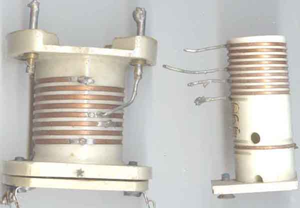
Here the invention of the dust iron cores by Hans Vogt brought
the solution. Instead of varying the capacitance of the tuning
circuits these were fixed and the inductance varied by using
variometers. Inside the sphere-shaped coils on their ceramic
formers were cores of sintered dust iron. The variometers of the
master oscillator and final amplifier were ganged and tuned by a
single knob.
The receivers of the FuG 10 installation were also housed in
cubes with dimensions 200 x 200 x 190mm. They were high-grade
superheterodynes with 11 valves of the universal pentode type
RV12P2000.
An important aspect of the FuG 10 was its serviceability.
Complete units and/or parts of it could be changed in very little
time by minimally trained technicians. All modules could be fixed
to the mounting frames by turning two fasteners through 90
degrees. The units - receivers, transmitters and all other parts
- were automatically connected via flat cables, similar to the
ones now found in computers, to the junction box, fixed to the
fuselage.
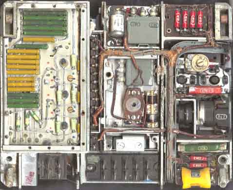
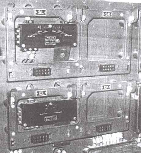
For ground station use the units were fitted to a frame that can
be seen in Photographs 3 and 4.
RB
More about FuG10 transmitters on page 30e
 |
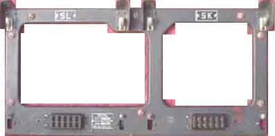 |
Receivers, transmitters, remote control box for
the antenne tuning unit and
other units can be easily removed from the frame by loosening two
fasteners.
Electrical connections are made via multipole plugs and sockets.
[FuG10].
Some socket connections
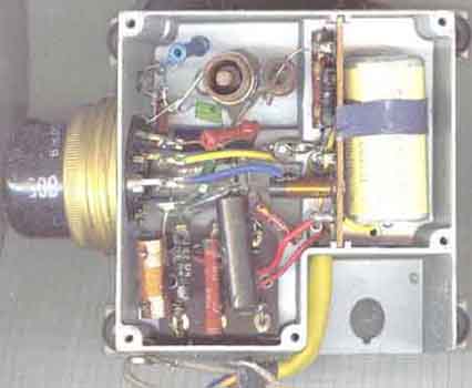
Die-cast boxes were also applied in BC-equipment just after WWII,
here is
shown Telefunken UKW1C "VHF add-on". Click on the
picture for more details.
 e/m
e/m
BACK
Last update: 2005.01.28