Torn.E.b/24b-305 version 1938
Trykkleif de LA5FH (to be checked when LA6NCA returns the papers)
Torn Eb:
Artikkelen s. 23 og 24 flere steder:
Zk fo Rs Cs Ls
fig 1
fig 2
fig 3
fig 4
fig 5
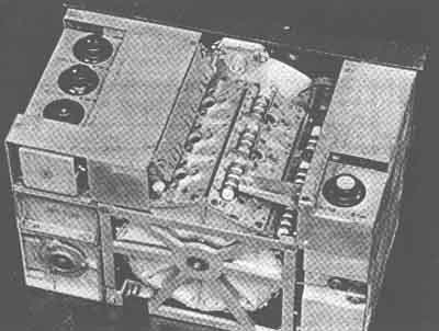
photo 5
Radio communication equipment, as used by the allied forces during World War II, is well known among collectors and lovers of wireless equipment from the past.
Communication equipment that was used by the German forces during the war is much less known; that applies not only in the United States, but for Europe as well. This may look remarkable as that same Europe formed one of the main theatres of war. Why was it that so much of the allied equipment was left behind after the German forces capitulated that war surplus shops flourished for many years after, whilst at the same time German equipment has been relatively rare right from the start of the post war period?
Not because these units were manufactured or used in limited quantities. One of the main suppliers of radio equipment, the Telefunken firm, employed some 40,000 workers, spread over 350 different locations, by the end of WW II. How many sets of different categories were made is unknown to the author. But it has been put on record that of one radio used in tanks, the so called "Bogegerät", some 180,000 units were manufactured.
The reason that so little of the vast German production remained may well be that the allied forces that occupied Germany after it collapsed ordered that all radio equipment that was found was to be demolished. By the end of 1945, and the beginning of 1946, this order was changed in that equipment remaining at that time was not to be destroyed but dismantled. The components that resulted from that action formed the basis for German production of consumer radio equipment, a production that came to a faltering start at that time.
Not only thousands of radio's ended under the crash hammer, also all drawings and other documents that supported design, development and production of the equipment went the same way so that hardly a trace of it was left. What we know about the background for the wartime production of German radio equipment has been reported orally by some of the leading men who were involved. Please don't get the idea that the author condemns the decision to destroy all wartime German equipment. It was a completely understandable and justified decision. But it does explain why most of us radio amateurs, both in the USA and outside, are in general rather unfamiliar with the communication equipment that was used "on the other side." And that is certainly to be regretted as this equipment was of exceptional technical perfection and beauty.
Of course some German WW II radio equipment escaped destruction and part of what remained found its way into the hands of collectors, some of whom specialize in German radio apparatus. By sheer coincidence your scribe came into contact with one of those specializing collectors, Arthur Bauer, PA0AOB, who lives near Amsterdam. Arthur owns a most beautiful collection of German WW II radio equipment. When I met him for the first time in 1977, his collection comprised more than ninety items. By today it must have passed a hundred easily. It is certainly no simple feat to bring together so much of this rare equipment. Arthur scans the whole Europe for it and he has his contacts in most of the countries of our part of the world.
PA0AOB not only collects the German equipment, he also uses it for his contacts with fellow amateurs.
Photograph 1 shows Arthur, PA0AOB, making a QSO via a powerful German transmitter of WW II vintage. The receiver at the left of the transmitter will be described later in this series. Single sideband does not exist for Arthur, of course. Only c.w. and a.m. and a system of teletyping over radio, invented in the twenties by Dr. Rudolf Hell. The machines that use this system are called "Hellschreiber" ("Schreiber" means "writer" in German). The system is different from RTTY as we know it in that the characters are transmitted in a form of simplified facsimile (FAX). The received characters are printed on a paper tape as they are received as "pictures". The charm of it is that the receiving machine does not decode the characters as in normal teletype. The decoding is done by the operator who interprets the "pictures" on the tape as characters. Interference and or fading on the radio path can never result in a wrong character being printed. The picture of the characters may become blurred or smeared by the interference. But due to the supreme capabilities of the human eye and brain a lot of Interference can be accepted before the received characters become unreadable. The price for this immunity against interference is increased bandwidth. The signal is about six times as wide as a radio teletype signal of the same transmission speed in characters per second. This is partly compensated by the fact that the Hell system of teleprinting does not need FSK as modulation mode. Simple on/off keying of a c.w. transmitter gives fine results. So in the end the Hell signal occupies about the same bandwidth as a teletype signal of the same speed.
The Hell system is commercially obsolete. But it has been revived by a group of European amateurs, who possess the machines for it. Photograph 2 again shows Arthur typing on a "Hellschreiber" as they were extensively used by the German forces during WW II. Your scribe is so lucky as to have a "Hellschreiber" on loan from PA0AOB and so he meets Arthur and several other amateurs in Europe every Sunday afternoon on forty meters, using this nostalgic way of communicating. One of the members of the "Hell group" is Hans Evers, DJ06A/PA0CX and he described the Hell system of teleprinting in Ham Radio Magazine, December 1979 ("Heilschreibers rediscovered").
But back to the subject of this series: German WW II communication receivers. In the next section we will describe some general characteristics of German radio equipment. 0ne feature we will discuss in more detail: a quartz crystal intermediate frequency filter with continuously variable bandwidth. This type of filter was used in several receivers of the superheterodyne type. Following it we will discuss two receivers of the tuned radio frequency variety and two superheterodynes.
You are probably surprised that the Germans used t.r.f. sets. But they certainly knew how to make them in superior form. A great advantage of the Straight set is that spurious responses are non existent, even in the presence of extremely strong signals as In shipboard use, where several, transmitters may be active at the same time receivers are operated. Another advantage from a military point of view is that the t.r.f. set does not use oscillators and so the chance of location by the enemy using a direction finder on spurious radiation of the set is negligible.
This article could only be prepared thanks to the assistance of PA0AOB. Not only did he make the receivers available for photography, he also gave the author the opportunity of using some of the sets in his own shack for a considerable period of time.
The fact that PA0AOB could provided the original technical manuals, of exact replicas of them, was also of great help in the preparation of this article.
Fig 6??. Simplified circuit diagram for the receiver
General Characteristics of
German Radio Equipment
The oldest company that manufactured military radio equipment in Germany is undoubtedly Telefunken. During the first World War (1914-1918) this firm supplied radio communication equipment for the German army. Production of military equipment was forbidden in Germany under the Versailles treaty that ended WW I. But when Hitler came to the fore in the early thirties the situation changed drastically. When general conscription was announced in 1935, production of weapons and other war material came into full swing. New communication equipment was to be developed and produced. Again Telefunken was the leading firm. Also Lorenz, a German branch of the American ITT concern, started extensive activities in the field of military radio. In 1937 the German government invited tenders for a new radio for military aircraft. It came as a shock to Telefunken that Lorenz emerged as the winner with their FuG 10 set. This consisted of beautifully made separate receivers and transmitters for different frequency bands that were combined in a rack. Photograph 3 shows part of a FuG 10 installation, at the left a long wave receiver, in the center a short wave receiver and at the right a short wave transmitter. The antenna was matched by a remote controlled tuner, that is visible in photograph 1 on the shelf; it is the box with the rounded corners at the left. The superiority of Lorenz was especially evident in the mechanical engineering of their equipment. In the following years the dividing line between Telefunken and Lorenz products became less clear as equipment was manufactured under mutual licensing contracts. Also other big firms, like Siemens and companies in countries occupied by Germany took part in the production.
We will now take a look at the German radio equipment and see whether we can find some characteristics that make it so unique and different from similar gear used by the allied forces.
In the first place we observe the tendency to use a minimum number of different types of radio tubes. Most of the receivers used the same type of tube in all stages! This posed some tricky problems for the designers. We will meet an example of this later on. From a logistic and maintenance point of view it is of course a clear advantage to limit the variety of tubes to the absolute minimum. The tubes were especially developed for this military equipment. They were miniature types, certainly gauged by the standards of those days, and very robust. The tubes fitted special sockets that completely enveloped them and in which they had to be inserted top first. Nevertheless, the hope that a few types of tubes for all receivers and transmitters would suffice was not fulfilled; by the end of the war some 100 different types could be found on the lists of .military tubes.
Another feature of German radio receivers and transmitters is that the designers certainly were generous as to the total number of parts used, especially if by doing so potential sources of trouble could be avoided. One finds, e.g., decoupling devices and screening liberally applied in all stages of a receiver or transmitter. Another feature is that even the simplest piece of equipment has the possibility of having its proper operation checked by the user. A built-in voltmeter with selector switch to measure voltages at different parts of the circuit is the minimum always found. Sometimes quite elaborate built-in operational checks can be encountered. Again we will meet an example of this later on in the series.
The most striking characteristic of German equipment is no doubt the mechanical part of it. The traditional chassis, so familiar to radio equipment of the past, was never used as such by the Germans. Instead they filled the space in a cabinet in three dimensions. The circuitry of a radio set was divided in a number of units, "modules" we would call them in our day, that could be easily removed and replaced. Usually such a module took the shape of a completely screened box of cast alloy that made it extremely stable, both from a mechanical and an electrical point of view. Inside the box was divided in completely screened compartments that housed the different stages belonging to that unit. The units were combined to a complete set by mounting them into a frame, again made of cast alloy. The electrical connections between the units consisted of multipole connectors on the modules, mating with similar devices on the frame. The whole became an extremely strong combination with almost ideal electrical characteristics and easily accessible on all sides for servicing. The whole assembly slides from the front into a sturdy cabinet that in itself already forms a solid and stable basis.
This battleship-like construction also works out in a negative way; most of the German pieces of radio gear are extremely heavy, no doubt partly due to the fact that aluminum was not used for the boxes and frames. The exact composition of the alloy is unknown to this author, but very likely zinc formed a major component of it.
The moving parts such as gears, tuning capacitors and switches are masterpieces of mechanical engineering. Moving a coil turret from one position to another, e.g., is done by a big solid crank and it feels like opening a safe or the door of an expensive oldtime automobile. Regardless how complicated the mechanical devices, they can always be dismantled in a few seconds by loosening one or two screws. That the mechanical linkage can be complicated is evident when one realizes that, e.g., variable capacitors or band switches that are ganged are sometimes found in different modules that can be easily taken out of the frame, in spite of the mechanical gears. Nevertheless the mechanisms operate with extreme precision. Examples that demonstrate these principles will be shown when we come to the discussion of the four receivers that will be covered in this article.
The German sense for perfection, that is reflected in even the smallest details like terminals, is also demonstrated in the instruction manuals that come with the sets. These not only provide very complete information for the operational use of the set, but also the maintenance man finds everything he needs to know for performing his job properly.
That the designers certainly had service ability of their products in mind is already clear from a simple visual inspection of a radio set. One finds, e.g., screws that are surrounded by a red ring. These have to be loosened to remove a complete unit (module). If one wants to take a unit farther apart the screws marked with a blue ring have to be removed. It is these details that make it a real joy to dissect a German WW II radio.
As announced in the previous section we will now discuss one feature in more detail: an intermediate frequency crystal filter with continuously variable bandwidth.
Such filters are found in several German communication receivers and they were made for different i.f.'s. The "Köln" receiver for instance, that we will meet later, has an intermediate frequency of 1 MHz. The bandwidth of the crystal filter working on this i.f. can be varied between 0.2 and 10 kHz!
The circuit diagram of this filter is shown in fig. 1. The filter is positioned between i.f. amplifier tubes. A second filter of the same configuration follows the tube on the right. Upon casual inspection one could easily conclude that this filter is of the familiar type to be found in many popular American communication receivers and introduced in the early thirties by James Lamb in his "Single Signal Superhet." These filters feature a sharply peaked response plus a rejection notch that can be moved up and down in frequency by means of "phasing capacitor" 03. But this conclusion would not be correct. The German filter exhibits a real bandpass response, that is to say a flat passband and symmetrical filter slopes at the transitions between pass and stopbands. How is it possible to realize such a response with just a single quartz crystal resonator?
For explanation we turn to an elementary form of bandpass filter, the so called "constant-K type," depicted in fig. 2. This filter consists of two parallel tuned circuits connected by a series tuned circuit. All three circuits are resonant at the same frequency fo, the center frequency of the pass band. The circuits are supposed to be ideal (without losses). The filter must be fed from a source with an internal impedance ZK and loaded by an impedance ZK. ZK has a different value for every frequency in the pass band and stop bands. Because this is almost impossible to realize in practice the filter is used between a source with internal resistance R and also loaded by R. R is taken as the value of ZK at frequency fo,
In fig. 3 a constant-K bandpass filter is shown that has been designed for a center frequency of 1 MHz and a pass band of 10 kHz wide, just as the crystal filter in the "Köln" receiver. The component values for L1 and 01 have been taken equal to L1 and 01 in fig. 1 for the "Köln" filter. Now look at the series resonant circuit L2C2; don't 02 and L2 have "impossible" values? Indeed, especially L2 could never be constructed with a self-inductance of 3.6 henry at 1 MHz. To produce a capacitor of 0.007 pF isn't simple either. But wait, let us take a look at the equivalent electrical circuit of a quartz crystal resonator, as shown in fig. 4. This consists of a series tuned circuit and a parallel capacitor that represents the capacitance of the crystal electrodes. The values for the elements of the equivalent circuit shown in fig. 4 are typical for a 1 MHz crystal. These values are very near to those of the series circuit C2L2 in fig. 3! So it looks like we could replace C2L2 by a suitable quartz crystal and so obtain a bandpass filter at 1 MHz with a 10 kHz wide pass band. But what about the earlier statement that the elements of a constant-K filter were suppose to be without losses? RS of 5 kilo-ohms in fig. 4 certainly looks like a high loss. But be careful with that conclusion; what really matters is the Q of the series tuned circuit. And Q is equal to the reactance of Cg or Lg at 1 MHz, divided by Ry and that works out to a Q of 6280, That value is so high that the crystal, acting as the series tuned circuit, can be considered lossless. And how about the losses in the parallel tuned circuits L1C1? The coils in these circuits certainly don't have such a high Q that they can be considered to be without losses. But as shown in fig. 3, these circuits have to be loaded by resistors of 113 kilo-ohms, and part of this loading can be provided by the loss of the circuits themselves. Isn't that beautiful? The loaded Q of the parallel tuned circuits has to be equal to the center frequency FO of the filter, divided by the width of the pass band. In our case 1000 kHz divide by 10 kHz; So the loaded Q of circuit L1C1 must be 100. with good quality components this can be easily obtained. If the actual Q of the circuits turns out to be higher than 100, extra loading by resistors (or by the output impedance of the preceding tube and the input impedance of the following tube!) can be provided.
So now that we have seen how the single crystal filter can really work as a bandpass filter let us go back to fig. 1, the filter of the "Köln". We see several extra components, as compared to fig. 3. In the first place the crystal is not connected between the upper ends of the parallel tuned circuits, but between taps on the coils. This is done because it would be very difficult, if not impossible, to manufacture a quartz crystal resonator where the parameters of the electrical equivalent circuit have exactly the values required. So in practice the crystal is measured to find out what the actual values of CS and LS are and then the proper tap on the coil is computed.
The required value for C2 and L2 of the series tuned circuit changes with the square of the tap ratio on the coils. If for example the taps were made halfway up the coils then the value of C2 would be four times as big and of L2 four times as small as in case of connections to the top of the coils. So by selecting proper taps on the coils the actual crystal can be matched to the filter. In the "Köln" several taps are available, obviously to cater for manufacturing tolerances in the crystals.
Another new element is trimmer capacitor C3. This is a neutralizing capacitor for the parallel capacitance of the crystal and its holder. Once properly set it needs no further adjustment.
You will also note that the anode of the tube feeding the filter is connected to a tap on the coil. That is obviously done to decrease the loading of the input circuit of the filter by the output resistance of the tube. Undoubtedly the designer had selected this tap in such a way that the correct value for the loaded Q of the input circuit is obtained. The grid of the tube following the filter is also tapped. From a loading point of view this seems unnecessary as the input impedance of a pentode at 1 MHz is very high. But the tube is controlled by the automatic gain control
system. And under influence of the a.g.c. voltage the input capacitance of the tube changes slightly and this could detune the output circuit C1L1 of the filter. Hence the tap. This leaves us with the function of C4 and C5 to explain. They are sections of a two-gang variable capacitor, but a special one; the construction is such that when one section increases in capacitance, the other section decreases by the same amount. Now assume that at a certain position of the capacitor the input and output circuits of the filter have been aligned to the same frequency. The filter then acts as a bandpass filter of 10 kHz wide in our case. Now turn the capacitor, say in such a direction that C4 increases and C5 decreases. This means that the two parallel tuned circuits become detuned from 1 MHz by equal amounts and in opposite directions. Now the whole circuit is no longer a proper bandpass filter. Indeed what remains is a crystal, acting as a series tuned circuit, connected between two impedances. These impedances become lower as they are detuned farther from 1 MHz. The result is a narrowing of the passband that ultimately approaches the response of the crystal alone, which is a very narrow one. Because the input and output circuit are detuned in opposite directions, the response always remains symmetrical. There you are; a crystal filter where the passband can be smoothly varied between a few hundred cycles and 10 or more kiloHertz by simply rotating a single knob!
In the "Köln" and other receivers as well, two of these filter sections were used in cascade, separated by an i.f. amplifier tube. The sections of the capacitors for varying the bandwidth are in that case combined to a fourgang unit.
It is a remarkable fact that this beautiful solution to the problem of obtaining a continuously variable i.f. bandwidth in a receiver seems to have been lost with the disappearance of German WW II communication receivers from the scene. The system has been used in some post war German receivers, e.g. made by Siemens, but the system in general was almost forgotten until about a year age. Credit goes to Hans Evers, PA0CX/DJ0SA, for having it revived in an article in the Dutch amateur radio magazine Electron of July 1979. Hans, for many years, has owned a German receiver in which a crystal filter of the type described is used with excellent results. Triggered by an article in a German magazine on the alignment of such filters, Hans finally found out how the filter really worked. The explanation given above is correct and has been proven by Cas Caspers, PA0CSC, who calculated the response of a filter according to fig. 1 with the values of Cg and Lg of the crystal inserted on an digital computer. The calculated response conforms very closely to the measured one.
It should not be difficult for the homebrewer of today to make a crystal filter according to the old German principle. One only needs to know what the parameters of the equivalent circuit are for a crystal that is to be used in the filter. These can be measured In a setup shown in fig. 5, thanks to Hans Evers. All that one needs is a signal generator, a v.t.v.m. and a resistor. In order to read small frequency differences with sufficient accuracy an electronic frequency counter is almost a must. From the crystal parameters, the values of C1, L1 and the proper loaded Q of the input and output circuits of the filter can be computed with formulas that can be found in for in stance the ARRL Amateur Radio Handbook. For the variable capacitor with counteracting gangs we could probably use two varicaps on which the control voltage acts in opposite ways.
It is perhaps well to explain that the success of these early crystal filters is for a large part due to the fact that the Germans knew how to produce stable high Q coils, using powdered iron cupcores and such at a time when in other countries air coils were still used as a rule, with a simple powdered iron tuning slug used on others.
Fine coils were not found exclusively in the r.f. and i.f. parts of German receivers. In the variable frequency oscillators of transmitters coils can be found in which silver turns are burned into ceramic coil formers. As a result these oscillators show a remarkable mechanical and electrical stability. According to PA0AOB this technique reduces the temperature coefficient by a factor of 200, as compared to a conventionally wound coil. The same construction techniques were used in the manufacturing process of trimmer and fixed capacitors in tuned circuits. Now that we know something in general about German radio equipment from WW II days it is getting time to take a closer look at some of these fine radios.
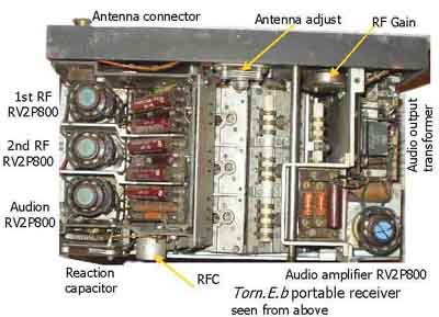
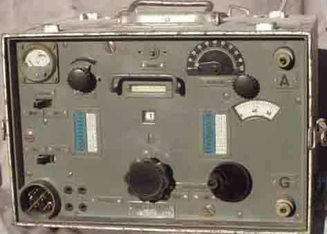
Tornister-Empfänger b
We will use the original German designation of the receiver we are going to discuss now. Photograph 4 shows a front view of the set. You see that the set consists of two units above each other. The cabinets - meant to be carried on the back of a soldier - that house the units are called "Tornister" in German. Actually in photograph 4 you see two half "Tornister", one housing the receiver and the other the power supply. "Empfänger" is the German word for receiver. And the letter "b" in the designation simply indicates which receiver. Mostly the designator was shortened to "Torn E b" and that is what we will use. The Torn E b was created around 1935/36. It was in general use with the German Signal Corps, but also at higher army staffs, police and traffic control authorities. It was a popular set, produced in great numbers and one of the few sets that found their way to amateur service in Europe in post-war stations.
It Is a tuned radio frequency (t.r.f.) set with four filament type tubes that were run from a 2 volt battery at 0.2 a. each. So the whole radio consumed about 0.8 a. from the battery. The anode current came from a 90 v. dry battery at a consumption of about 12 ma. It was also possible to generate the h.t. from the 2 v. battery via a vibrator unit and that is what you see in photograph 4. The vibrator unit is on the bottom shelf of the lower cabinet. Still another possibility was to run the whole set from a 12 volt automobile battery, also with a vibrator for the h.t.
The set covers the frequency band 97-7095 kHz In eight ranges. The actual coverage of each subband is as follows: