
Boatanchors
II
** Amateur radio equipment mods are found in chapter B **
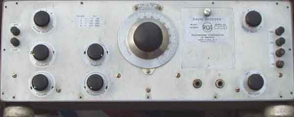
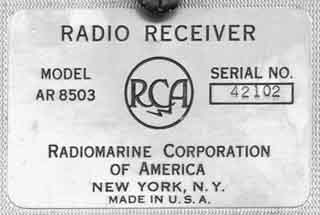
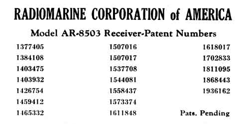
RCA AR8503 VLF Radio
communication receiver.
Frequency coverage:
| Band | |
| 1: 15- 40 kHz | 3: 100-250 kHz |
| 2: 40-100 kHz | 4: 250-600 kHz |
Valves: 3x 6K7 + 6F6.
Type 1V2:
RF amplifier + Regenerative detector + Audio amplifier + Audio
output stage.
Manufacturer: RCA Radiomarine Corporation of America, New York,
N.Y
[From NRHF auction
2003.10.19]
 |
 |
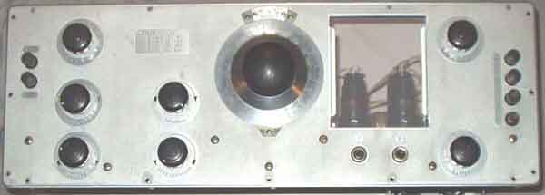
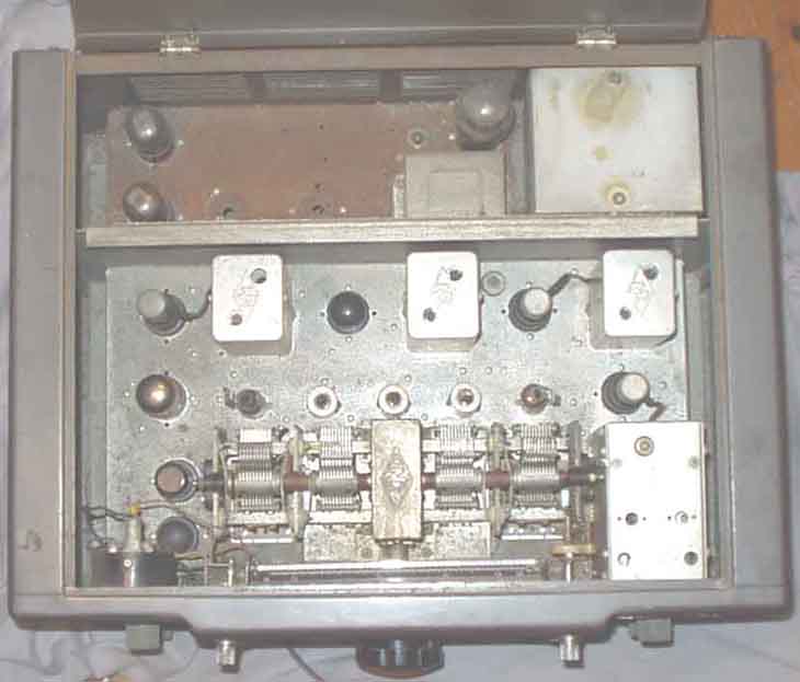
RCA AR8503
chassis front, with open window
 |
 |
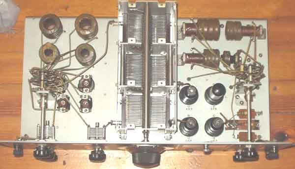
seen from above
The receiver
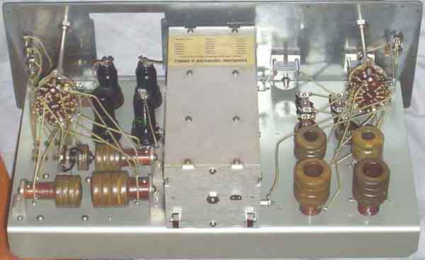
seen from rear
It is two sets of different
coils to the right, and the third set of coils to the right for
band 1 and 2. The first set of
coils are tuned with the capacitor at the front, the
second are tuned with the section at rear, they are supposed to
form a tuned bandpassfilter,
and the third set is tuned with the center capacitor.
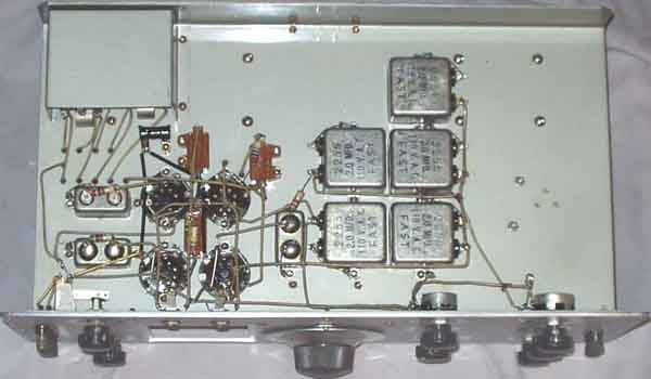
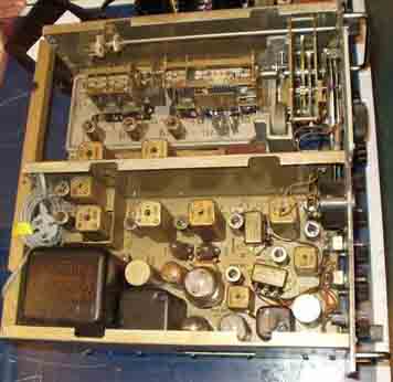
The receiver seen from below.
The 3rd set of coils for the highest bands (band 3 + 4) are
located at upper left side of the picture.
Connections: +90V, +22V, +6V, -BA, ANT/GND.
Simplified circuit diagram
for the receiver (schematic).
Note: The set of coils are screened
from the other (under chassis, while the others are above).
None of the coils have iron cores. Also note the unreasonable
large value for 6F6 cathode resistor,
but I checked it. Cathode resistor for the last 6K7 is 5.5k.
The trimmer is connected to the first tuned circuit - not the 2nd
as drawn.
 |
 |
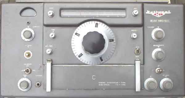
National HRO-50T amateur radio receiver with matching speaker
[From NRHF auction
2003.10.19]
National HRO-50T seen from above
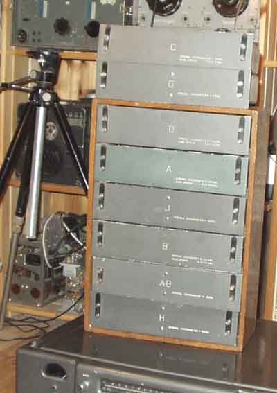
Have the following coil plug-in's:
| Band code | General coverage | Band spread |
| J | 50-100kHz | |
| H | 100-200kHz | |
| G | 180-480kHz | |
| C | 1.7-4.0MHz | 3.5-4.0MHz |
| D | 3.5-7.3 | 7.0-7.3MHz |
| B | 7.0-14.4MHz | 14.0-14.4MHz |
| A | 14.0-30MHz | 27.0-30MHz |
| AB | 25-35MHz | |
| AD | 50-54MHz |
Wanted: "Band F" (480-960kHz), plug in coils module
Manufactured: 1951. The coverage seems to be somewhat different
from what Fred Osterman claims
Circuit complement:
6BA6/EF93 1st and 2nd RF amplifier, 6BE6/EK90 mixer, 6C4/EC90 HF
Osc., 6K7 (EF39) 1st and 2nd IF amplifier,
6J7(EF36) BFO, 6H6 AVC/Det, 6H6 ANL, 6SJ7 1st Audio, 6SN7 Audio,
2x 6V6 Audio output, 0B2 108V stab.
Rectifier 5V4 ++ , it seems to be somewhat unclear and printing
mistakes
IF: 455kHz
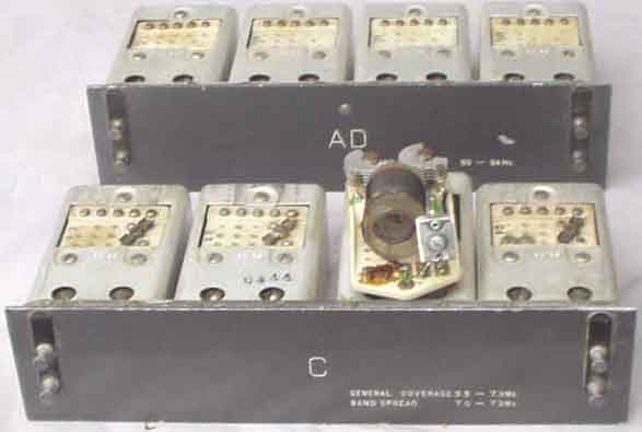
HRO50T. Plug-in coilpacks with one section
demounted (3.5-7.3MHz)
see pg-f12 for SSB-conversion
 |
 |
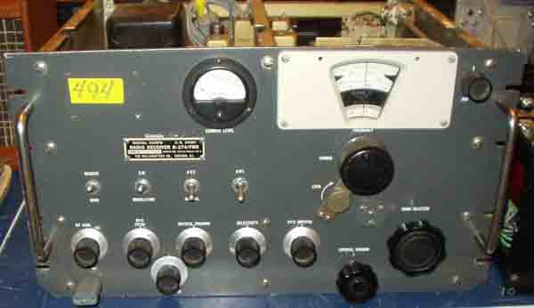
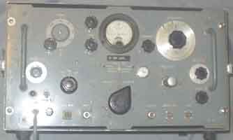
Hallicrafters R-274/FRR (=
Hammarlund SP600)
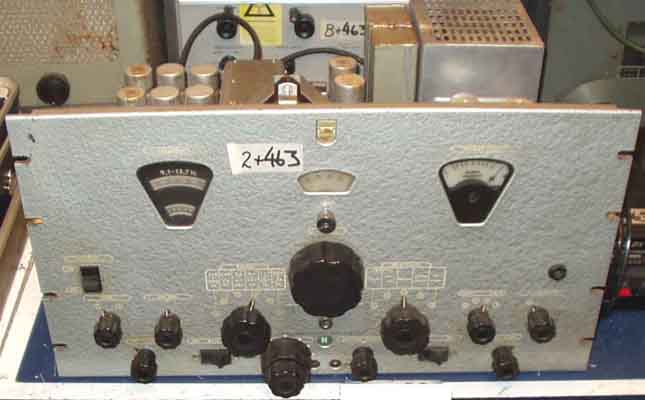
Philips BX925 Radio communication receiver
Have been curious about this receiver, since it was seen in '67
when I was in the army at Alta.
Glad I left it to another because all decoupling capacitors were
defective and must be replaced.
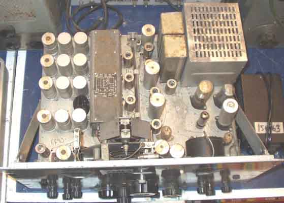
Philips BX925
Many of the round "electrolytic capacitor looking"
boxes are supposed to be IF transformers.
The receiver is mentioned in Fred Osterman's book "
Shortwave Receivers - Past and Present",
it has 75kHz IF,
Valves: 8x EF93 (6BA6), EK90 (6BE6), 3x EAA91 (6AL5), 2x EL90
(6AQ5), 5Y3GT, 0D3.
| Ranges: | |
| 210-540kHz | 9.1 - 13.7 MHz |
| 1.45-3.6 MHz | 13.7-20.7 MHz |
| 3.5 - 9.1 MHz | 20.7 -32 MHz |
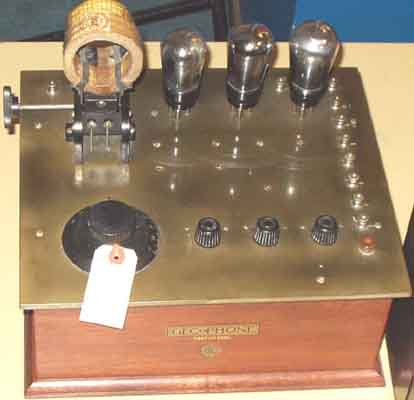
Couldn't resist bringing this picture of an old
radio ( http://www.nrhf.no/ )
[From NRHF auction
2003.10.19]
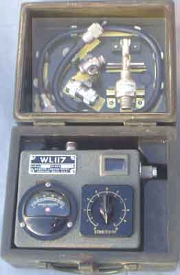
WL117 - possibly a microwave meter(?),
has micrometer tuning
Have no idea where I got it from.
HP623B, 6cm signal generator
Further notes:
Mods for Lorenz 6P203
Communication receiver on page b71 and f12
Modifications for Siemens Receiver 745 E310 on page b72 and f12
| I enjoy
collecting these items and and investigate into the
techniques. I will show them on my website for others to enjoy. I am not interested in selling them, however - please do not ask. Instead, I hope to help others who collect this type of gear and would like to hear from them. MailWasher: All incoming mails are filtered using MailWasher, so please use an intelligent title so it is possible to distinguish between friends and spammers. |


Updated: 2004.10.30