
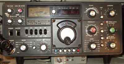
Yaesu
FT-902-DM Mods
most of the
mods applies also for FT-901
Bought FT-902 from LA6LCA in 1988, and it hasn't had any faults
at all. Only problem is intermittent
PCB edge contact problems, but they are easily cured with
windscreen wash liquid and vaselin. It is not
regarded as any problem that it has valves, they last very long -
as provided that you are not a fool
who sit on the key and tune very carefully. I would have
preferred sweep tubes as they last even
longer than 6146B, but spares have never been a problem, and the
future was planned many years
ago. An OM told me that his 6HF5's in Galaxy V mkII had lasted 19
years, and still were 90% of
full rating - this is in spite that he was very active! Bought an
FT-901 the other day for $125.-
as I needed a replacement for FT-7, but it was soon sold to a
friend who had to replace
his FT-101ZE. I am told that the worst problem with FT901/902 is
that the electrolytics
in the power supply may sometimes short, particularly those for
higher voltages.
Block schematic for the IF section of FT-902
(FT-901).
This is the key to understanding signal levels and how the
signals are routed
dependent on the different modes.
FT-902 (FT-901) IF passband
information
IF frequency schematic showing carrier frequencies at the IF on
the different modes, this is very important
to understand which frequencies are on RF compared to audio for
RX and TX
FT-902 (FT-901) RX audio problem
The first mod I did was to improve the audio. It sounded
awful, particularly bad with internal speaker,
I once had an FT-101B and knew it doesn't need to be so bad
quality, FT-7 also works fb,
but it is easy to cure. Just change the C511 in PB-1705A
to 47nF (.047). Fortunately it is conventional
component here, another Yaesu transceiver has 0.1µF
instead of 0.01µF capacitor fitted - as a
fault, but
it was SMD type, so it is two hours procedure to remove and
replace.
FT-902 (FT-901) keying and the Key-click problem.
I suppose FT-901/902 isn't among the
worst transceivers in this matter, but I'd
made up my mind to check the key circuit long befor I put it on
the air for the first
time. Some serious construction (it is not called design!) faults
were traced, with different
timeconstant for key-down and key-up
The ideal keying has
same resistance for charge and decharge of the time-constant
circuit.
I used this principle for 2m beacons LA3VHF and LA6VHF where the
actual keyed unit
was the two last stages of a PYE exciter, but usually it is not
so easy to implement a simple
circuit, but it is easier ways to do it.
 |
 |
3f) Improving keying for FT-901/FT-902. I always wish to
have a crisp and clean cw signal, the received reports indicate
that the result was good. It was some problems encountered,
because the time constants for KEY-UP and DOWN would be quite
different if only a capacitor was added, so the time constants
needed to be divided into two parts with diodes to increase
timeconstant when needed for a symmetrical keying shape. Suppose I have marked all changes with read
colour, but it might be some more component values, they should
be correct as they appear on the circuit diagram.
2) The key circuit isn't easy to understand, so I put a copy of
it to the right, and at least, you may see the pin 16 connection
at upper right (pin 14 goes to mode switch!).
PA secondary emission and
flash-over protection.
It is also another problem with the screengrid circuit for
6146B's. The power supply is protected against flash-over from
anode to screen grid, but secondary emission in the valve could
cause damage to the valve. This may be allright to do in times
when valves are easy to obtain, just go to any shop and pay some
amount of money because you choose to protect the electrolytic
capacitors instead of 6146B's. But now is 6146B's worse to find
than electrolytic capacitors, so why not protect both?
The problem is a diode (D01) in series with L04 on the PA board -
PB-1715 (No.17). A better idea is to connect a 10k resistor
across the diode and a varistor from screengrid to ground og in
the power supply, suggested type is SIOV14K150 which will limit
the voltage to 240VDC.
I've never experienced any problems, so my circuit might work, or
it wasn't needed, but I am not interested to prove it.
The power amplifier board PB-1715 (No.17), see more details on
next circuit diagram
The handbook is not correct, it is a power reduction on 28MHz
with a 2k2 resistor og the bandswitch. Here is shown my
modification of the screen grid circuit.
FT-902 Speech Processor mods
Improving the FT902 speech processor. The original circuit
had little effect, so I added 1N4148 diodes in anti-parallel.
The PROC. LEVEL also had little effect, this is greatly improved
using a P-type JFET. 2N5462 will work, but J177 is much better.
On-the-air reports have been very convincing, it is no distinct
clipping, and I am told that it is usually no problem to use the
RF-clipper (processor) in local SSB QSO's on 80, 40, 6, 2m, 70
and 23cm bands. It is approved by otherwise very critical
friends,
like Morgan SM6ESG, although he don't like my old Microwave
modules 70cm SSB transverter, hi.
The modification is described in more details in Technical Topics
(G3VA), Radcom
FT-902 (FT-901) Reduced RIT-range (Receiver
Iincremental Tuning)
The first and simple solution to reduce the range, particularly
valuable for CW operation
FT-902 (FT-901) Mode-dependent RIT range
Usually it is practical to have different RIT range for CW and
SSB, HF and VHF operation,
here is a circuit which suits my needs with 1.5kHz for CW and
5kHz on SSB, and most part
of my operation with this receiver has been CW and SSB on 144,
432, 1296MHz bands.
FT-901/902 with
transverter:
RF output level is quite high with FT-200, FT-250,
FT-101B, FT-901, FT-902. Suppose it is 100mW, while
most transverters hardly needs milliwatt level drive. Some
transverters are constructed for high drive level, but
I don't see the point, so I've always modified it using a 1000W resistor in series with 2p2 capacitor,
instead of the original 10pF from PA-grid circuit. The larger
capacitor may load the grid circuit and
tuning on higher bands may be upset. Also
connected a 10K resistor to the transverter terminal, such
that +12V follows the signal during transmit, it simplifies the
arrangement, no need for PTT lines,
and PTT lines to external equipment is very bad practice, if they
are grounded the external
equipment may start the transmitter and cause problems.
FT-901/902 Transmitter modification to drive a transverter
"RX-antenna"
modication.
Made external RX antenna connection for the FT-902
(FT-901), similar system to those I made for FT-250 and
FT-101B earlier. A cable from RX side of antenna relay goes to a
BNC connector board, and another
cable goes back to the receiver input. So I may choose between
which receiver I'll listen to, possibly
Drake 2-B or Drake R-4C, or use FT-902 with a transverter.
A simplified circuit shows what was done with FT250, FT101B,
FT902 to provide RX-ANT
output and input so I can use which receiver I want with FT902
transmitter, and use FT902 RX
as a separate receiver for another purpose without any risk of
transmitting into the RX circuit.
This is important feature for use with transverters, and often
one receive on another band, than tx,
only 14 or 28MHz is common.
FT-902 (FT-901) transmit level
adjustments.
Originally the transmit drive levels varies very much. FM has the
highest drive level. Decided to equalize the
drive levels for the different modes, some minor modifications to
different boards are necessary
A better
application for the 'AMGC' switch.
The AMGC has little practical effect, it was
mentioned by DL1BU when reviewing the FT901 transceiver in CQ-DL

Choose between SSB- and CW-filter in cw-mode
 |
 |
The AMGC switch comes to practical for selecting between SSB and
CW filter, but few extra components are
needed to activate it. When the switch is operated the voltage in
base circuit (see schematic above) is pulled
down from 12V towards +8V, and a 12V relay is energized. One
might have used lot of time to look for
an 8v relay, but I had a small 12V relay, and it draws much less
current than an 8V type. It is usually a good
practice to measure which voltage the relays need to operate, and
which voltage it falls back on, so it is often
possible to use a 24V relay on 12V, but it must usually not have
higher operate voltage than 9V for safe operation
on 12V system, and 6v for 9V operation.
Logarithmic
S-meter for FT-901/902.
S-meter deflection is far from ideal, and some
improvements were made with the original circuit, but
it was never somewhere near the desired result. I would accept
that an S-unit varies between
3-7dB, which is not much accurate, so I looked for other ideas
It was a need to make more accurate measurements with the
receiver. An S-meter where an S-unit could be
anything between 0.5-7dB is regarded as useless, but believed to
be a feature for the average operator who
wish to give 59 reports to everybody. This circuit has 70dB range
- provided it is set up correct, and this is
more than you need, I've never experienced that the meter peaked,
but I've got some complaints
that I don't give a 59-report to an unreadable station.
It should be noted that the gain and current of the input stage
must not be set too low, it is better
to attenuate the signal with resistors in the drain circuit! I
suppose the reason is that the dynamic range
for the amplifier is reduced when it doesn't draw much current,
so it will not drive sufficient when
signal to pass is "strong". The minimum voltage from
MC3356 output is 0.6V. It is a bad idea to
use a simple diode here, the voltage drop with varying current
may vary between 0.4-0.6V, you may
loose indicating range. It is much better to rely on a transistor
B-E junction diode, or just use an
emitter follower. It also solves the problem with time constant
in the detector, but this is an unsolved
problem, it could be better. It is also a problem with FT-902
that it is some false signals in the
IF and the logaritmic detector cannot be set to indicate signals
lower than 2µV on the receiver
input connector. MC3356P is a very sensitive device. Another
device used for similar purpose
is Philips TDA1576, but I suppose it won't work properly here
because it is not sensitive enough,
or perhaps is it just what one need to operate the input stage
with some decent current and gain?
PB1726A (FT902 VFO switch) obscure circuit diagram
Had a fault and needed to follow the VFO signal, but the
handbook is obscure on this point.
Perhaps the worst is that details shown in the handbook are
incorrect, so it was only one
thing to do; loosen the board and inspect the pcb to draw my own
circuit diagram
FT-902 overall installation
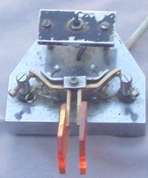
PTT facility on the paddle for CW operation.
Have mounted a PTT-switch on the paddles for my shack. It
simplifies operation and you have 100% control, a
nd easy to switch between RX and TX, and back again if you wish
to check that you are not transmitting when you shouldn't.
Since it will always be a time delay when you throw the button to
you can start transmitting it is no need for time delay, but
it may be another idea if you use no-control cw meteorscatter
operation
The paddle is good quality, but haven't the faintest idea who
made it, bought it from a very drunk Finnish OPR at
Aannaboda VHF meeting, who may be the producer, and definitely
wanted to buy it back the next day, but I refused.
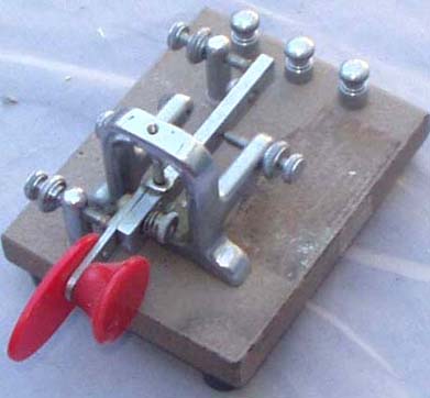
The Vibro-keyer paddle.
Since I worked at Rogaland radio in 69-70 we had some ideas what
was the best paddles and it was two different makes to choose
between, Autronica and Vibrokeyer paddles. Bought my own
vibro-paddle, and used it for a year, until I got a better German
construction
which also could operate SQUEEZE, and it was used until 1987,
when I got the Finnish paddle mentioned above. Vibrokeyer is a
part of the
older vibroplexer. It seems possible to drill some holes in the
iron block, and mount a PTT switch on the paddle, but I keep it
only as a reserve.
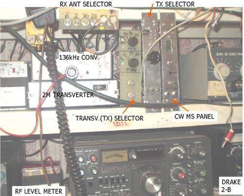
Operation control units
The units mentioned above for operation on HF, 6m, 144, 432,
1296MHz. IF for 6m is 14MHz, while it is 28MHz for the higher
bands.
For 13, 6, 3cm an IC202 is used to drive.
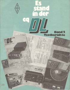
Es stand in der CQ-DL, Band 2,
Testberichte
A really very interesting book from DARC showing
testreports by DL1BU for the following equipment:
Atlas 210/215, CRF320, Drake R-4C, Dressler D200, FT-221, FT-301,
FT-901,
IC-202S, IC-211, IC245E, IC-280E, IC402, IC-701, KDK FM 2015R,
KDK FM2016E,
LT470 (Braun), Multi 2700, REIS SE200XL-A, SB-104, SE301 (Braun),
TS-520, TS-820,
Vergleichtest FR101, FT-220, FT221, HG70D, IC201, Multi2000,
Multi2700
Die Testberichte in Band 2 finden ganz großes Interesse bei den
Mitgliedern. Der Band kostet einzeln DM 9,-.
Beide Bände können für DM 14,- bezogen werden.
Skandinavisk språklige artikler (Scandinavian
language articles):
FT-901-DM Modifikasjon (2) Noiseblanker .......LA3ZL AR 79-08-212
FT-901/902 Forbedringer (2) ..............................LA8AK
AR 90-07-206
FT-901-DM Modifikasjon (1) Klikk og NB ........LA3ZL AR 79-06-175
FT-901/902 Nøkling...........................................
LA8AK AR 89-06-165
FT-901/902 Forbedringer (1).............................. LA8AK
AR 89-02-038
FT-901/902 Noise-blanker ..................................LA8AK
AR 89-02-039
FT-901/902 Processor (RF-clipper)..................... LA8AK AR
89-02-039
FT-901/902 forbedringer for HF/VHF.................. LA8AK OZ
93-07-407
FT-901/902 Forbedringer af - ..............................LA8AK
OZ 93-07-407
FT-901/902 rettelse for....................................... OZ
7/93 OZ 93-11-661
FT-902 Xtal kalibrator kan gi intermodulasjon .......LA8AK AR
89-04-105


2005.03.05