b73
Racal RA 17 mods
Links to pages for similar equipment:
b 71 Lorenz 6P203 Communication receiver
b 72. Siemens Funk 745 E310 "Rainbow receiver"
Valves:
CV 138 = EF91/6AM6, V1 XO, V2
harm gen, V5 1st VFO, V6
37.5MHz amp., V10 37.5MHz amp., V12
2nd VFO, V19 BFO, V22 Audio
o/p, V23 AF o/p
CV 140 = EB91 = EAA91/6AL5, V18 AGC & TC, V21
Det & NL,
CV 453 = EK90/6BE6 V11 3rd mixer, V13
CAL
CV 454 = EF93/6BA6 V14 1st IF amp, V15
CAL, V16 2nd IF amp, V17 IF o/p
CV2209 = 6F33 V4 Harmonic mixer
CV3998 = E180F V3 RF amp, V7
1st mixer, V9 2nd mixer,
CV1327 = GZ34 (GZ33) V20 Power rectifier
ECC189= 6ES8
A receiver is no good if it is no room for improvement!
Suggested SSB modifications:

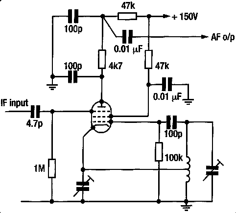
The simple product detector/insertion oscillator using a single
pentode used by G3RZP in his rebuilt HRO, suitable for fitting
into many older type receivers designed before the introduction
of amateur SSB, see Radcom TT January 2004 p45, and January 2005
p.75 (G3VA)
(6AM6/EF91 or 6AU6/EF94.)

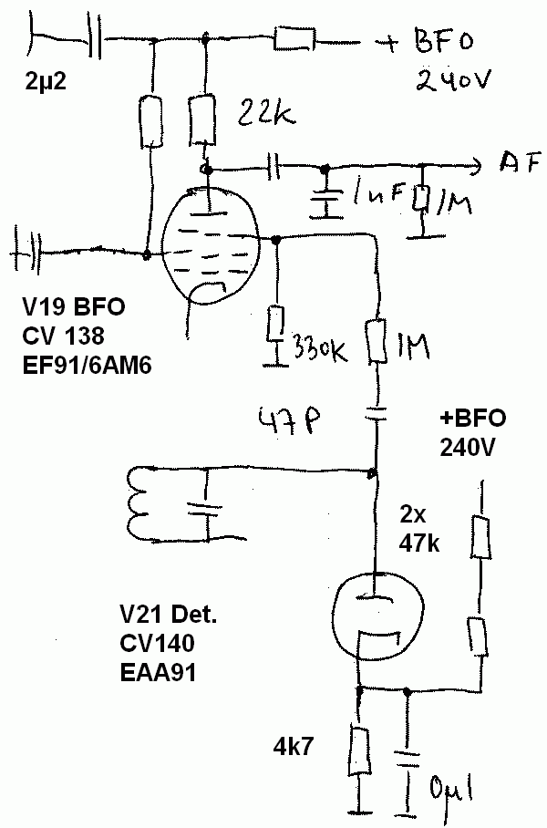
Suggested modification for ssb after Peter, G3RZP in Racal RA17.
The envelope detector is biassed off during CW/SSB reception and
will not produce any background noise.
To switch the audio a relay seem neccessary to switch the signal
from product detector to R134. To divide the power into two 0.25W
resistors they are in series (LA8AK)
Peter adds: A point that didn't come out in the
write up by Pat Hawker is that this approach depends on the fact
that the AM detector usually had around 10 or even 20 volts
applied to it to minimise distortion. Thus the low conversion
gain by putting the signal on g3, attenuated by a small series
capacitor, still gives adequate AF output. As the amount of BFO
leakage to the AGC diode is small, the BFO doesn't (or
shouldn't!) overpower the AGC in the way it usually does with
feeding the BFO into a diode detector. I believe a number of US
amateurs have fitted product detctors in things like the SX28 by
using a 6SA7 pentagrid, but you don't need this degree of
conversion conductance.
I've suggested a voltage divider on the input to product
detector. It might be a reason to keep some signal level on the
anode side to avoid noise from the power supply and add some
attenuation in the output as well as on the input to the product
detector. It seems no good idea to keep the high screengrid and
anode voltage as in the original construction (see Peter's
proposed circuit), but reduce them at least to under +100V.
Back
Last update: 2005.01.28

