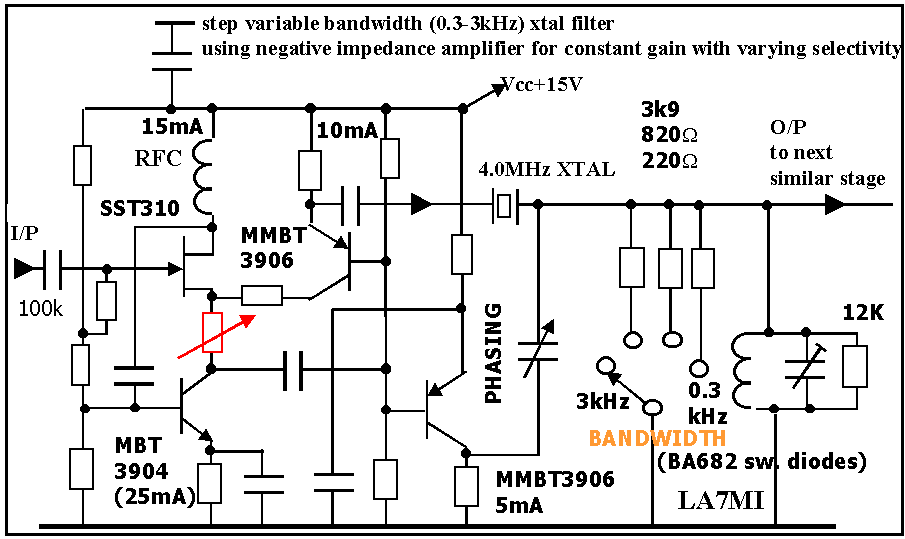
C.42: LA7MI 4MHz variable
bandwidth xtal filter
based on negative impedance-amplifier.

The filter is based on a HP spectrum analyser (1980), but the
original circuit diagram was almost impossible to understand and
Stein (LA7MI)
had to go his own way trying to use the idea building a negative
resistance amplifier.. The original filter operates on 21.4MHz
with variable
bandwidth between 1kHz and 5kHz. LA7MI's circuit uses 4MHz xtals
and may be tuned in set to bandwidthes from 0.3-3kHz. The
switch uses BA682 switching diodes. The xtals were from a bunch
of 20 where he measured them as accurate as possible and used 4
which
had maximum 10Hz difference. The trimpot is adjusted such that
the gain is equal for all bandwidthes, and the phasing potmeter
is adjusted
using sweep equipment, other efforts may seem impossible to align
the filter and may only cause an endless effort with little
success.
The stop-band selectivity is only 25-30dB for one section, so you
need 4 similar stages in a decent spectrum analyser. For higher
bandwidthes
he uses LC-filters.
The unit is built on a 7x25cm pcb in SMD technique.
MMBT3904=2N3904=BC237B, MMBT3906=2N3906=BC557B, SST310=J310.
I have no more component details, it is all based on some
telephone conversations and a sketch he sent me via snailmail
after he mentioned
it yesterday and I said I was curious about the circuit diagram
for the negative output impedance amplifier. The amplifier is
adjusted to
reduce the loss resistance of the xtal, so if it had -47ohm
output resistance and you put a 47 ohm resistor in series with
the output from
the amplifier the total impedance is zero.
Notes which are not signed otherwise comes from
LA7MI.
He has a soldering iron, but no email, and is reached by
telephone nr +47-55-902392.
He will be very pleased to receive
comments, the postal address is: LA7MI Stein Torp,
Tollbodalmenning 34, N-5005 Bergen, Norway
Update: 2004.07.12