
d 31) VHF/UHF/SHF-beacons
A. Antenna topics
C. Amateur radio
experiments
D. VHF/UHF experiments
Technical
standard for the beacons.
![]()
LA6LCA and I have decided that we will only support beacons using
A1A mode,
and we have built most of the beacons in Norway and North
Denmark.
We have some bad experience with foreign beacons which is very
difficult to
identify because they use their own sort of FSK-keying. Beacons
are used to
see where the condx goes, fast IDENTICATION is a must, not
several attempts.
And the beacons shall send ID twice or more - at least once per
minute.
Many has experienced that they don't know if it is a spurious or
a beacon they listen to
Table-theoreticians at IARU are convinced that frequency shift is
best,
but with A1A you may reduce the heat by up to 60%, and it means
that
the beacon may not suffer from break down in a hot summer day;
and
of course - the most important is the electricity bill. Suppose
some Swedish beacons in our neighbourhood also follows this
principle....
Another technical requirement is that the power amplifier should
withstand 4 times the
power you run, OZ1UHF (70cm) uses a 30W AP-2000 PA with an output
power of 5W.
Included
the locator with the callsign on my LA3VHF and LA3UHF beacons
back in
1978, and since then many other have followed this practice. Got
some complaints,
that "the beacons talks too much", but why should I
care? It is
a lot of persons with opinions,
but only very few capable of giving any contributions to doing
things.
2m
CWMS beacons LA3VHF (Mandal) and LA6VHF
(Kirkenes)
the beacons use similar low noise 12MHz XO as the one
decribed below, but have +12v supply.
PYE Westminster boards were available in larger quantities, and
the exciter is very good. It delivers
150mW which is fed to a quasi-linear power module, like Philips
BGY43 or BGY36 for 146-174MHz.
Part of the exciter circuit is shown below. LA3VHF uses a PYE
W15FM chassis, while LA6VHF is built into
PYE T30FM chassis, with the original power amplifier, but the PA is
modified. Often an
unmodified stage
will hardly deliver much more than 12W, while the modified easily
produces 20-25W RF. And it is just by addition
of some resistors and capacitors to balance the power to the two
power devices. It is, however,
very important to use all possible ground from the pcbs to
chassis, and not use the floating ground,
it may only cause bad spurious problems.
It was suggested to build some beacons for high speed CW
meteorscatter, where LA3UHF serves
mainly as a test beacon to check the equipment, while LA6VHF is a
DX-beacon
It is important to avoid any sorts of key-clicks to a
practical extent. The keyed signal is therefore passed through
at least a second order active filter with a linear amplitude
modulator for the two last stages of the exciter.
Good key-up attenuation is easily achieved. Single keyed
transistor is possible on lower frequencies, but not on 72 and
144MHz. So the two last stages have the +Vcc isolated
from the rest of the board, and fed to the key-line.
Tr4 is doubler from 36 to 72MHz, and Tr5 is doubler to 144MHz,
while Tr 6 runs cool with 150mW output.
Suppose another device than 2N3866 was used in an earlier
version. 2N4427 might be a better alternative, but since the
RF output requirement is only 150mW it is not important. The
exciter board is very easy to adjust, although
the first stages and modulator has been removed from the board.
The key-filter and driver must be linearly
operated, it means that the input swing must be as such that the
transistors conducts during KEY-UP, and they must not be
saturated at KEY-DOWN. I don't have the
values here,but will return to this when the documents are found.
The keyer is rather complicated and
isn't suitable for modern application, you would probably do it
easier with some microprosessor.
Only my 13cm beacon has xtal oven, none of the other beacons
have. And it is not at all necessary for 2m,
probably not for 70cm, and the 23cm beacon always stabilized near
the proper frequency, so it was not
a problem.
 |
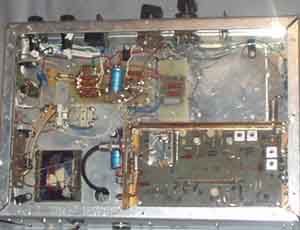 |
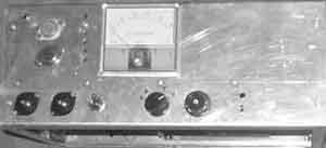
The remainder of my 2nd LA3UHF beacon (1983) - without
the callsign generator
SM6HYG built the box. Used an integrated amplifier and
tripler from 144.293 to 432.880,
only problem is that inspite
of low local activity it is always somebody who complaints,
and it was almost impossible to attenuate the 2m signal. The
amplifier was also very hot,
had a fan (with signal added
to the callsign generator to indicate if the fan was running),
and
it ran most of the time. Just an argument against IARU beacon
recommendations!
Changed to SRA FN/FB205 transmitter in 2000, this transmitter had
been used for LA3UHG,
but was taken in for service and I had some problems to reinstall
it again, so it was better
to sell it as a 70cm beacon
Low-noise XO for 12MHz used with my beacons, based on an article by
DJ2LR
this version is used since
1978 with LA3UHF, LA4UHF, LA6UHF, LA9UHF with SRA transmitter (negative
supply voltage).
LA3UHH 13cm beacon, constructed in
1986 by LA6LCA.
The beacon is still operational and have not failed once.
It is located at Tromöy, Arendal (JO48JK).
LA6LCA built the RF part and I built the logic. The varactor multiplier EN5A was
made by NERA Bergen.
Have built the following beacons
and will try to find some more constructional info later:
LA3VHF, LA3UHF, LA3UHG, LA4UHF,
LA6VHF, LA6UHF, LA9UHF,
also built the logic for LA3UHH, LA5TEN and LA5UHF
Have also contributed to LA5VHF, TF3VHF (TF8VHF?)
The beacons are based on the following equipment:
SRA FN205 (C400) base station: LA3UHF, LA4UHF, LA5UHF, LA6UHF,
LA9UHF
PYE W15FM: LA3VHF (2nd version of the principle made for LA6VHF)
PYE F30FM/T30FM: LA6VHF
CW
Meteorscatter beacons:
LA3VHF (1200LPM), LA6VHF (1500LPM)
Because of very much available surplus from NERA Bergen, we rely
upon such equipment
for microwave beacons (LA3UHH, OZ1UHF), some multipliers have
been sent to Germany,
Nederland, Sweden and USA. We have very good experience with
their microwave multipliers.
SRA
FN/FB-205/CB-405 Exciter.
Got over a douzen
transceivers from the maintenance center, they were supposed
to be faulty, but I never found anything wrong. The only fault
was the very complex
way it was mounted with lot of voltages from the psu, and the age
- they are designed
in the mid 60's. I used the transmitters for UHF/SHF beacons and
the transceivers -
without power amplifiers - for packet radio nodes. They were very
stable,
but needed some more txdelay than more modern equipment.
I have 25 years experience building beacons and require very low
sideband noise. Constructed the 12MHz xtal osc in 1978 (see
above) as the original
oscillator in another exciter was experienced bad, and have used
this
construction since. The SRA exciter is also modified, all
modulator
and 6MHz stages are removed, so it is not much left. The key
logic is
operated on -8V, the exciter on -18V, and the multiplier on +25V.
SRA
FN/FB-205 216MHz amplifier has a very bad design fault. It is extremely
difficult to tune, but it is easy to improve. The problem is the
bias network
(V316=AAZ17, L330 ferrite bead). Remove them, it is better
applications for such diode!
Use a 100W 1/2Watt resistor instead. Experience
shows that a 0.25W resistor
will only last some years, so it is better to search for a 0.5W
carbon type.
The unit is then very easy to adjust with simple tools like a
Bird Model 43
wattmeter.
Note that V311=2N4073 is a rather unusual device, and you cannot
expect
to use a normal transistor here, it has quite high base impedance
and low
capcitance, a normal device might totally ruin the Q-value.
Output power is somewhat low, have heard of one unit with more
than
8W RF output, but you should be happy to achieve 5W on 432MHz.
The power input is nearly 30W, but it is a varactor stage, too.
When used as 23cm beacon it was some chassis radiation, it was
cured with a plate
fixed to the mountin frame - covering the output stage - almost
too simple to be
true!
Remote
control for beacons.
The intention for the simple remote control unit is to
switch off the beacon when it is mounted
somewhere you have no regular access to. It was important since
the beacon was
very strong in JO37SX when we had DXpeditions, but it should not
be possible
to control it from distances larger than few hundred meters or
possibly 1km. It uses a TR-switch
which doesn't load the TX signal, and the receiver senses signal
between the dots, so
it needs a 1750Hz tone modulated signal lasting few seconds to
stop the transmitter
and a code (series of at least 8 dots in 1750Hz tone) is sent
after some seconds
when the tx is halted. Since nobody else knew about it, it was no
problem even
when it was a quite busy 2m channel, but scanners wouldn't
usually find it fast
enough.
Simple TR-switch used for LA3VHF beacon's 2m remote control
receiver
the l/4 length isn't critical at all - 30-33cm
RG58/U or PTFE-cable will work on 2m and 70cm.
Beacon frequency was 144.880MHz and the remote control receiver
operated on 145.0MHz.
The diodes are RF switch diodes, possibly 1N4148 may work, but
who has so few components?
LA3VHF
beacon remote control RX.
RF board U4 from Philips CMT 9551-151-12206 2m Mobilophone. It
could be any 148-174MHz
receiver, I don't like the Philips equipment as a transceiver,
but the RX is a smaller block
which may live its own life and therefore suitable for my purpose
to be installed in a beacon
assembly. Since the unit was converted 20 years ago I don't have
much info, just found this
circuit.
Note that RF amplifier stage is removed, and a 4.7pF bypass
coupling connects between the sets
of coils - still sensitivity was somewhat high. 50µVpd for 20dB
quiteing is desired sensitivity.
145.000MHz RX xtal was available, and not interesting for other
purposes so it was chosen.
Traffic on this channel is not too high, since it is only for
emergency repeater.
Component board
LA3VHF
beacon remote control RX.
Tone decoder and timer. Bock diagram
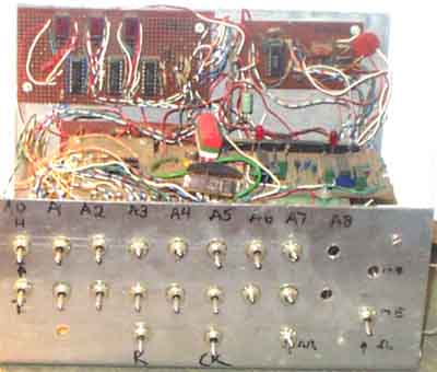
Eprom burner constructed in 1978 to program Fairchild
93427 4x256bit eprom used in a douzen
different beacons I built for Norway and Iceland.
LA5VHF 2m beacon, LA5UHF 70cm beacon

BACK
VHF beacons, shf beacons,
uhf beacons, 10m beacon, CW beacons
update: 2004.06.22