n12) Understanding broad-band ferrite
transformers used in solidstate Power Amplifiers
(by LA7MI Stein Torp - 1994)
The author is retired design engineer from A/S
NERA BERGEN, a radio link manufacturer for over 50 years, and he
has worked there for over 40 years. He has been a very important
origin source for the ideas I have presented in several magazines
over the last 35 years.
In general, the ferrite loss for small
signal does not give the proper values for transmitters. So you
may waste hours with math only to learn that the results were
wrong, or perhaps you stick to the theory and insist that the
math is right, but the material was wrong, and make a complaint
to the manufacturer. But it is easier to try finding practical
conclusions with experiments, then it is also easier to test any
unknown material which may be offered at very low price, instead
of being dependent on Amidon cores which in many cases are very
overpriced. Philips wrote some document around 1970 showing
curves which proved the problem that the small-signal theory is
wrong for transmitters. The Philips document seems unknown to
several designers we've asked, so it might be a thought to show
it here later.
Have bought books by Helge Granberg, and also read the Motorola
application notes, but I am surprised how much is described using
obscure references to math which most readers may not understand,
it is much easier than he describes, and I do not agree with many
of the conclusions made in several articles. It is easier to find
important parameters using some practical experiments, this opens
for use of inexpensive sources of surplus materials, in
particular the Philips core mentioned below has been available at
no cost in larger quantities for many of my friends. I've also
been to surplus rallies in Los Angeles and London and experienced
that a lot of very useful cores have found little interest among
the crowd. I am surprised that some readers have not access to
curves which are shown in Philips data books as early as 1970,
and have drawn the wrong conclusions with a lot of math. If you
don't agree or like to exchange opinions I'll be pleased to
receive a letter via post, address below.
Two types of transformers can be found in linear amplifiers:
The transmission line transformer, and the
conventional transformer.
The transmission line transformer isu used for large bandwidth
ratios (Fmax/Fmin). This transformer is difficult to make.
In modern RF-power amplifiers we find the conventional
transformer type consisting of primary and secondary windings
wound on a ferrite core.
To build a transformer we must know a little about:
1) The turns-ratio to give the wanted impedance trasformation
2) loss in the ferrite core due to magneticfield (generates heat)
3) how many µH for minimum operational frequency
4) coupling between primary and secondary to cover maximum
operational frequency
5) effect of DC current in the windings
6) how to increase max. operational frequency with capacitive
compensation
Ferrite losses
Let us start looking at an ordinary mains transformer.
 |
The current in the primary sets up an alternating magnetic field in the core. The loss is the core depends on the strengths of the magnetic field. |
 |
When we connect a load to the secondary winding the priary current will increase. Question: Will the larger primary current set up a stronger magnetic field in the core? <No>.. |
For all practical purposes the magnetic field is independent of
the transferred power. This means we can investigate the loss in
a ferrite core by winding a few turns, and connect the winding to
a suitable signal source.
80m highlevel RF signal source
This 3.7MHz 0-1.5W RF output Colpitts oscillator using 6BQ5/EL84
tube is extremely useful for investigating loss in ferrite cores,
and also as a higher level signal source for testing linear power
amplifiers. (also see page m3).
See page-n15 for notes about DC saturation
How to test a ferrite core for power loss.
Increase the level and the temperature in the core will increase.
Find the voltage for 20°C temperature increase.
Example 8. This core can take 4 volts per turn.
Some actual ferrite cores for 2-30MHz PA's have permeability in the range of 100-1000
 10.5 mm OD, 6.9 mm ID, 19.5 Long Philips 3122 134 90783 Ferrite grade 4A4 permeability 500. 4v per turn at 80m band gave 20°C increase. 1 turn = 0.9µH |
 Amidon FB 43-2401 Ferrite grade 43, permeability 850. 1v/turn on 80m band gave 20°C increase. 1 turn = 0.35µH |
Formula to calculate the load
impedance.
8W output and (Uce-Usat) = 10V gives R load = 6.25 ohm
The load resistance of the two transistors in push-pull is two
times (not 4 times) the load of a single transistor. A push-pull
amplifier with 16W RF from the transistors with 12V supply must
see 12.5 ohm load between the collectors. The output transformer
in the push-pull stage must transform 12.5 ohm to 50 ohm, the
turns-ratio is 2.
16W RF Push-pull amplifier
The inductance in the secondary must be: 10µH or more for
frequencies down to 3.5MHz, 20µH or more for frequencies down to
1.75MHz. (The reactance must be larger than 200 ohms at the
lowest frequency of operation).
Lower frequency limit for a broadband transformer
Without any loss in the ferrite we could be satisfied with 10µH
inductance in the secondary (50 ohm load) for operation down to
3.5MHz. In the real transformer we have loss due to the magnetic
field. As previously shown this limits the volts per turn. For
the 16 watt output rating, we will have 28..3V across the
secondary
Philips ferrite tube 3122 134 90783 (10.5 mm OD,
6.9 mm ID, 19.5 Long). Let us say max 3.5V per turn. We can use
1, 2, 4 etc number of tubes.
(We chosed this type only because it had been available here at
very low cost in larger quantites, somewhere else another type is
optimum).
Secondary winding (50 ohm load):
 |
One tube, 8 turns, inductance 0.9 *(8) ² = 28.8µH Lowest useful frequency = 0.6MHz |
|
Two tubes 4turns, inductance (0.9 +0.9) * (4)² =
28.8µH Lowest useful frequency = 1.2MHz |
 |
Four tubes, 2 turns, inductance (4x 0.9)2 ² =
14.4µH Lowest useful frequency = 2.4MHz |
 |
8 tubes, 1 turn, inductance = 2x 0.9 = 7.2µH this combination gives lowest frequency = 4.8MHz |
In the 16w push-pull amplifier we can use two or
four tubes in the transformer. The winding wire must not give
additional loss due to resistance and skin effect. With 16W RF
output the current is 28.3/50 = 0.57A in the secondary winding.
What happens when we double the
number of turns?
The transformer can now supply 56V RF. Doubling the voltage gives four times more power (4x 16
= 64W). Since doubling the number of turns gives 4 times greater
inductance, the low frequency limit is also divided by 4.
Power dissipation in a broad band transformer
A id4eal transformer has zero power dissipation. A real
transformer has two types of dissipations:
1) Ferrite losses. Can be reduced by reducing the "volts per
turn" rating
2) Ohmic losses in the windings. Can be reduced with heavier
wire.
Upper frequency limit for a broadband transformer
In a conventional transformer (not a transmission line
transformer) the upper frequency limit is dependent on the
coupling between the primary and secondary winding.
How to test a transformer for leakage-inductance?
| Short- circuit the primary |
 |
Measure the secondary inductance in "µH" = leakage inductance referred to the secondary winding (50 ohm load) |
| Leakage inductance |
Upper frequency limit without capacitive compensation |
Upper frequency limit with capacitive compensation |
Compensation capacitor across the secondary (pF) (50 ohm load) |
| 0.125µH 0.25 µH 0.5 µH |
15MHz 7.5MHz 3.75MHz |
60MHz 30MHz 15MHz |
25pF 50pF 100pF |
For proper performance we must
also put a capacitor across the primary winding. With a turns
ration of 1:n this capacitor must be n² larger than the
secondary capacitor.
Note: We must subtract the transistor output capacitance.
 |
 |
Testing a broad-band transformer by VSWR measurements
By measuring the returnloss (or VSWR)
we can optimize a broadband transformer. The primary must be
loaded with resistors = load impedance per transistor in the
push-pull stage.
Try to achieve better return-loss than 17dB or SWR better than
1.3:1.
DC current in a broadband transformer
 |
Feed the supply via a 'centertapped balun'. This method also improves the waveform at the transistor collectors |
DC can reduce the inductance in the windings, it is best to avoid a DC magnetizing component
DC-saturation (how to
measure DC saturation in a ferrite core).
For an Amidon FB43-4301 ferrite core the inductance
drops by 50% for 1.2At. 3At for 75% reduction. One should keep
the DC-current below the value of 0.5A to keep the reduction
below 10%. In the example above this rule is used, but the best
is to use push-pull arrangement and the DC magnitation is kept to
a minimum level. The inductance reduction is stored and the
effect is called remanence, cores used with direct current should
have air-gap, and several such cores exists for low frequency
power inverter applications.
As an illustration for measuring core
saturation this picture could be used. A DC voltage is applied to
one side, and an inductance meter to the opposite. Note the DC
current voltage needed to reduce the inductance by 10%. Say the
DC voltage is 1.25V, the current is 0.25A, and the ampere-turn =
2 * 0.25 = 0.5At (provided voltage drop over the winding is
negligible).
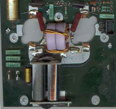
Output transformer in the 16W amplifier
 |
Note: No DC magnetic field in the ferrite core |
No DC magnetic fields in the ferrite
cores
Un-edited circuit diagram (no
available photo program)
The 16W power amplifier covering 3.5-10MHz
It is a plate to shortcircuit the two
metal tubes at the left side of the driver transformer
Block diagram for the homebrew
SSB transceiver in SMD technique
TX power 15W, RX NF 10dB
Document received from LA7MI in April
2004, and the note about saturation has been added in May,
the author has no email, but is reached by telephone nr +47-55-902392.
The postal address is: Stein Torp,
Tollbodalmenning 34, N-5005 Bergen, Norway
Comparing data for Philips og Amidon ferrite core material:
| Philips | Amidon | ||
| Type | Permeabilitet | Type | Permeabilitet |
| 4C65 4A11 3F3 3E25 |
125 700 1800 6000 |
61 43 77 73 75 |
125 850 1800 2500 5000 |
- LB8X
Tom
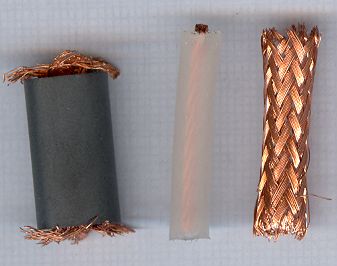
My comments about RF transformers where it is one turn consisting
of a brass tube, is this really neccessary, could a coax braid be
used just as well?
The ends could be solved, and you need no end plates (LA8AK)
Assessing unknown Ferrite Toroids (G3NYK)
See notes about bias regulators
and LA7MI 40W FET linear amplifier (n15)
![]()
Last update: 2005.01.08