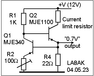
n14. Selecting reference transistor for bias regulator construction
Choosing proper reference
transistors for a bias regulator

It is important know that the sense device (Q1) hasn't too high
BE-voltage. In principle it should be as equal as possible to the
RF device, but it is often not possible to check this, so it must
at least work some way when the power amplifier is starting to be
tested. Some may have much higher than you think, BUY49 has 0.8V,
and as such is impossible to use here. The power device should
have high gain to avoid loading the collector voltage of Q1, and
as such varying the collector current. R2 may be used for minimum
adjustment of output voltage.
BE-voltage (open collector) for varying base current over some
time at 288°K (bold vs normal for 293°C) for
possible devices to be used as sensing devices.
Q1 should be mounted thermically as close as possible to the RF
power device, and Q2 should be mounted farther away from the
reference device so it does not add to the temperature, another
idea is to use lower supply voltage for Q2 to decrease the heat
further.
| Base current | ||
| Device (Q1) | 10mA | 0.7mA |
| 2SD235 | 600-643 | 543mV |
| D44VH11 | 663-676 | 598 |
| MJE340 | 663-676 | 572 |
| TIP29C | 640-663 | 546 |
| TIP31B | 625-640 | 534 |
| TIP41A | 646-662 | 546 |
BC547B ........814........../...688mV
Later found BD135 to be fb for reference device, and BDX33
(BDX53) to be most suitable to use in the regulator, they are
used in a Skanti 500W HF amplifier.
n12 Choosing ferrite cores for
linear amplifier (LA7MI)
n15 40W FET linear
amplifier (LA7MI)
d28 Nokia NMT450 100/200W amplifier for 70cm band (Norwegian text)
Updated: 2005.03.14