
Devoted entirely
to Amateur radio
Jan Martin Nöding
L1. VLF (136kHz) amateur-radio
constructions
Related chapters and
pages:
L2: VLF aerials and accessories
L90.Suggestions
for 135-137kHz TX VFO
C97. LF
ideas from Technical topics (G3VA)
M. Measuring
equipment
M31
LF/Audio instruments
g30.
Miscellaneous equipment, BC and audio
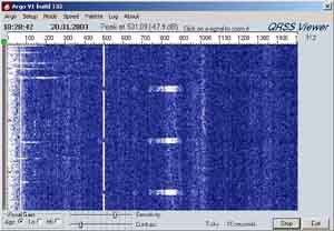
Using the program SIGVIEW.exe you may have a
presentation of the audio spectrum from the
receiver on the screen. Using a receiver with 3kHz bandwidth -
135.....138kHz would be
ideal to see what's going on below the noise on the band
Have a lot of possible receivers for VLF; Siemens E310,
Lw.E.a, BC453 etc, but the
problem
is that you need very fine tuning, so it is not so easy to modify
and old receiver for better bandspread,
but easy to build a converter or a new receiver. None of my
receivers had sufficient selectivity,
but adding the DSP-9 to the audio output may work satisfactorily
provided the band is reasonable
quiet (see NOTE*). Tuning resolution is also very important to
tune the signals with an accuracy of few Hz.
The first attempt to build a converter for 136kHz had 40673 as
first mixer and BC547 oscillator.
Signals were very strong, so much RF amplification is only waste
of ressources and produce
a lot of unwanted noise. It was the idea to build an SM5BSZ type
xtal filter using 59.995kHz xtals, but
I didn't succeed, and a simpler IF filter consisting of two high
Q-coils were used provisionally.
The sketches below show some of the attempts made to build a
receive converter
to use with Yaesu FT-902 (Receiver). The first version consist of
part 1A and 2B (1B is suggested
if you live away from Europe where S042 devices are hard to
find).
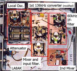
Early version of 136kHz converter uses 40673
mixer. 60kHz IF breakthrough was a problem, so it is added a
second coil to the input circuit to improve the selectivity.
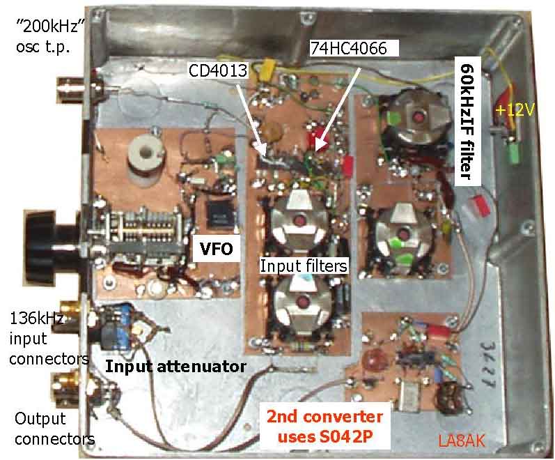
Picture showing the latest version of 136kHz converter.
In this business you just can't get
too many input/output connectors. Installed some BNC connectors,
but later preferred Conhex,
because they are free and available on lot of surplus equipment
and cables. But often must use
dividers to connect all instruments and receivers needed for some
experiments
Block schematic for the new 136kHz converter
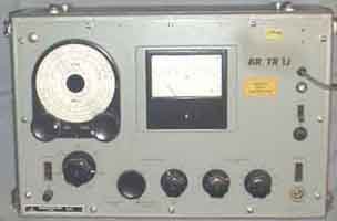
Using selektiver
Pegelmesser/Selective voltmeter as VLF-RX:
On some occasions - as for listening
to the Alesandersson generator on 17.6kHz, an extra audio
filter is not a good solution. I used Siemens D2006
with 3kHz bandwidth, but a noise signal around 18kHz,
almost covered the wanted signal, it was hardly 3dB S/N. The
17.6kHz signal was not weak, 0.5mV
from the active antenna in a distance of 350km from the
transmitter. Using 80Hz bandwidth crystal filter
improved the signal-to-noise-ratio by almost 30dB, see elsewhere
how to modify D2006 for suitable
pitch tone frequency, but it was impossible to listen to the
1500Hz beat tone as in original state!
It is no AGC and the dynamic level is only 20-25dB, so it is
somewhat complicated to use such instrument
to cover a larger band. Audio output is quite high and it is easy
to build an audio amplifier to drive a
loadspeaker.
The power gain for this simple dual-gate mosfet mixer is rather
high. It was soon learnt that in spite
that I didn't hear MSF when listening to 60kHz
(with the active aerial), it did break through the IF, and 40dB
IF rejection was neccessary with active aerial on 136kHz at this
QTH in (Kristiansand, Loc: JO38XC, South Norway),
therefore it is shown a two stage input filter.
Latest version: 1st mixer for 136kHz uses 74HC4066.
This is the actual construction in use now.
The 74HC4066 (Motorola or Texas) was chosen after a discussion
with LA8OJ, and he claimed he did
extensive tests and it was almost impossible to overload it when
running on 10-11V DC. Operating into
200W impedance the loss is mcuh lower than for 50W, and it has a
theoretical input
power limit of +18dBm. This is sort of controverse to do, but
still in accordance with the databooks,
so we don't understand why we should look for better and more
expensive devices when we can
use a readily available IC. The two-stage input filter may not be
necessary as it was with the
simple mixer, but it solved a problem, the signal to the mixer
must be balanced, and the use of
two stages instead of one, makes it easy to get balanced output,
instead of winding new
coils with links. 1.5mH coils (Q=700) were available in larger
quantity from surplus equipment.
A 7MHz direct conversion SSB receiver is planned using HC4066 -
based on commercial equipment
(uses originally 2x SA602), also a spectrogram receiver is
planned for 136kHz, but I am looking for a
455kHz 4kHz bandwidth ceramic IF filter, so details are not
clear. A program may be
downloaded and tested one month, the name is Sigview.exe
Local oscillator for 74HC4066-type converter .
The first local oscillator operated on 195-199kHz,
it is is difficult to ascertain that the signals are balanced,
som ideas were described in Technical topics,
Radcom adjust the balance, but I didn't succeed, so it is better
to rely on flip-flops. It is easier to build a
VFO on a higher frequency and divide to to 195-199kHz, since it
requires more readily available coils.
Little further is to be said, but I was surprised that only one
stage was needed to achieve good limiting.
BF314 were chosen since it is available free in large quantities,
but I suppose any 2N2222, 2N3904,
BC237, BF199, BF224 and many other types would do the job just
fine.
2B) 2nd mixer uses S042P (60kHz to 3627kHz).
This the actual circuit I use, based on a device which I
have few douzens of. It seems important to balance it, and 40dB
improvement were made. The xtal was
used since it was available, you could very well choose a better
xtal frequency, but when the HF transceiver
(FT-902 with separate input connector) has been set once.
On page c13 is shown another S042P type
mixer where 25dB carrier leakage was improved using the extra
resistor arrangement. Some data for S042P and E devices are also
shown further down the page.
2L) Alternative 2nd mixer (60kHz to 3627kHz).
Since S042P is an obsolete device, it is suggested
an alternative circuit using NE602, NE612, SA602 or SA612.
Suggested VLF up-converter after DK1OF 030 (UKW-Berichte Nr 1/76
S.35-50, VHF Communications.......?). There is no real lower
frequency limit, it depends only on the coil and capacitor
values, my suggestion is SBL1 or other inexpensive ringmixer
(SRA1, MD108, CM1 or other). The lowpass filter could have an
upper frequency limit of 160-170kHz to attenuate the BBC Radio 4
on 198kHz.
Pt301 is 136kHz input, Pt302 is IF output and Tr302 is oscillator
input, my suggestion is 2MHz signal from an xtal oscillator for
2136kHz IF output. A pcb has been available.
 |
 |
Iit is a lot of
good old instruments available, and they are usually easier to
repair than those digital black boxes which nobody seems to have
documentation for or cannot understand.
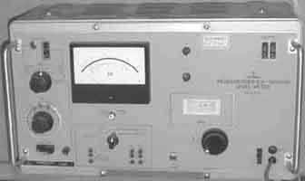
Siemens W56 (Pegelsender to the right) is a generator
(50kHz-30MHz), and Siemens 3D344 Pegelmesser to the left is a
selective level meter (1-1600kHz). Siemens instruments are
probably the best there is among such instruments, see further
notes about measuring instruments on page m1 and the following pages.
Notes:
Broadband amplfiers and RX
antennas, see page L2
ON7YD,
Amateur Radio, Longwave ressource page
Back to LF mainpage

2005.01.10