m1. LC- and Q-meters.
m1. LC- and Q-meters.
c.
Amateur radio technical experiments
m2. RF
detectors, level meters, attenuators, dummy loads, signal
dividers
m3. RF
signal- and power generators
m11 Grid
dip meters + xtal testers
m12
Power- and VSWR-meters
m21
Norwegian instruments
m22.
Old measuring instruments
m23.
Signal-to-noise-meter
m31.
LF/Audio instruments
 |
 |
 |
 |
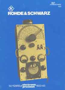
Several old constructions and instruments are still a good idea
to use today, the Rohde & Schwartz 50 years anniversary book
contains several stories about some of their oldest, but highly
appreciated instruments.
1.1)
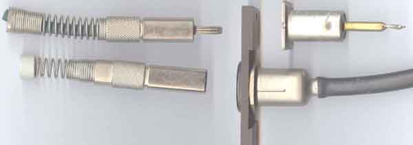
Some German LF/HF-coax connectors from the
50...60's.
Above is the coax connector usually found on CF
instruments from Wandel&Goltermann and Siemens, and below is
the Fernsehen connector which is practical for video switch
panels. I use them for selecting between HF antennas. (also shown on page m-12)
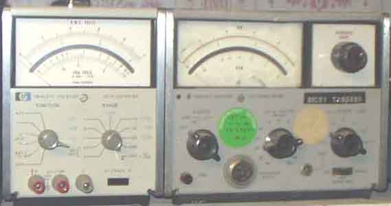
1.2) Analogue RCL-measuring instruments
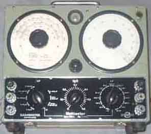
Radiometer MM1f, an old, but still very
useful multimeter to maintain!
 |
 |
Radiometer MM1f multimeter.
Modification in particular to achieve better reading between
20nH-2µH coil inductance. Note the series coil, it is the secret
why it is possible to measure inductance values down towards
zero. (Since it is a gif file it prints better than it seems on
the screen). It is usually no problem to find inductance values
with this instrument when the instruments fails to work. Also
have a digital L-C-R-meter and some Q-meters, but the old
1950-vintage instrument seems still worth to maintain
.
A suggested compensation for home-brewing instrument, to null out
the extra connection wires with alligator clips, in my case they
measure to 150nH
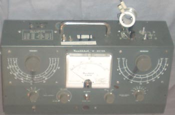
1.3) Radiometer QM1f (50kHz-70MHz in 8 ranges)
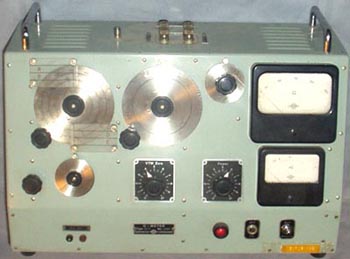
It seems sometimes difficult to use if you don't already know the
inductance or resonnance frequency. Won't modify as it probably
upsets calibration, the only modification is a mains socket on
the rear and a BNC skt for frequency counter. The screws for
device under test is bad design and it is often difficult to fix
the coil wires properly, they tend to fall out when screws are
tightened. Perhaps it was invented before they started to make
holes in the screws?!.
The Q-meter detector uses an EF6, see note further below
1.4) Build
your own Q-meter calibration coils
Received note (not edited): I can give you some detail if
you like using an Amidon core as an example. I would think the
"Q" will vary some with "doping" material
used to hold the turns in place, wire spacing around the core,
and consistency of the core material itself (maybe other
factors). I bring up the last point because these Amidon
"yellow" cores appear to be operational at a lower
range than their charts indicate even thought they mention that
larger cores tend to peak towards to low end of the range.
Amidon T-50-6 core, Permeability 8, Freq range 10-50Mhz, color -
yellow
Winding - 23 turns of #22 wire
Spacing - equally spaced around toroid
Doping - none
Inductance - 2.5uH
Results:
| Frequency (MHz) | Capacitance (pf) | "Q" |
| 7.9 8.5 |
150 134 |
340 350 |
| 9.0 10.0 |
119.4 94 |
355
355 |
| 15.0 18.0 |
41.5 28.5 |
340 296 |
| 19.2 | 25 | 284 |
73s Kees K5BCQ
Boonton 260A Q-meter:
http://www.qsl.net/k5bcq/qmeter/qmeter.html
#1.5) how to build
your own Q-meter
An idea how to build your own Q-meter, with
the shown ferrite core transformer you easily make very low feed
impedance I redesigned my Heath Kit QM-1
meter using this technique, and used a 6BA6/EF93 as grid
detector, based on the principle used for Radiometer QM1f, this
uses a Philips EF6, and I believe it is better than EF93 which I
ended up with as only modern alternative, while
EF94/6AU6 didn't work at all.QM1f uses a small resistor and
requires quite heavy excitation to achieve high enough drive, and
a thermocouple to measure the power. But this is much easier with
the described ferrite toroid technique, since you may measure the
level on 50W side.
Had some discussions with Dick Rollema PA0SE regarding detectors,
and he proved that 1N4148 type detector, didn't load the circuit
so much that it couldn't be used in a Q-meter, but of course it
depends on the frequency and minority carrier life time
#1.6)
The poor man's Q-meter
It was constructed as a comment to a SPRAT article to
demonstrate how cheap it was possible to make a coil measure
meter, suppose it could be built for less than £2.50, but
depends on what you have in your junkbox. American broadcast type
capacitors seems to be 2x365µµF, while the European standard is
2x450pF or 405+455pF (since we have the longwave AM broadcast
band, too), it is really not so important. With different
capacitors you may tune to resonnance and coils be calculated
when you know the capacitance. You use an 80m receiver and the
S-meter deflection indicates the Q-value. It is important to use
a good capacitor at C4, not such disc ceramic(!) type, the other
capacitors are not critical in other ways than that they may
influence the frequency stability. C9 should be small as
possible, since the signal into the receiver is certainly strong
enough, it consists of two insulated wire ends twisted together.
Suggested construction
on a piece of copper laminate using the dead-bug method
#1.7)
Heathkit QM-1. (140kHz-18MHz in 4
ranges).We bought some in 76 when they were offered at half
price.
It has reasonable accurate Q-readings, but I never managed to
align the frequency properly over the band. 6AL5 detector was a
problem, mine drifted, but somebody else believe the diodes could
be selected. Must admit that I used QM1 for several experiments,
and it is now far from the original, but possibly totally out of
calibration. Ended up with a 6BA6 detector in a similar circuit
to the one in Radiometer QM1f using EF6.
#1.8
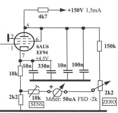
Q-meter. Grid detector using 6AU6 used with
Heath QM-1. The grid circuit must have dc return circuit via the
coil. The original is used in Radiometer QM1, but has an obsolete
type, EF6 which seems somewhat different from more modern type
pentodes.
Had some discussions with Dick Rollema PA0SE regarding detectors,
and he proved that 1N4148 type detector, didn't load the circuit
so much that it couldn't be used in a Q-meter, but of course it
depends on the frequency and minority carrier life time, so the
usage may depend on operational frequency.
#1.9) Q-meter construction
Q-meter. An alternative circuit: The primary consists of a brass
plates which passes through the toroid core.
It would be some improvement in coil loading if a voltage divider
goes to the diodes or an
RF amplifier could be used as buffer.
Notes for building your own Q-meter.
The first problem to consider is that you need a defined RF
voltage to use this technique for building your own Q-meter, the
second is perhaps even worse; the detector should not load the
tuned circuit. With 20mV excitation to the coil and Q=50, the
voltage on the hot side is 1V. So if you attach a 1/100 voltage
divider for connecting a 50 ohm amplifier, you will transform a
loss resistance of 10000 x 50 = 500kW
to the hot circuit and this is really too much for a good
Q-meter. I would reckon that an integrated circuit detector need
at least 100:1 detecting range, so it is not a good solution.
Dick Rollema PA0SE mentions the diode detector, and perhaps, but
it must be checked what the dynamic impedance is, and worse is
the diode characteristic which should be checked properly for any
detector intended to be used.
On the other hand, you may always build something which works,
but you don't know the actual calibration, and you may have good
use of it whether it is perfect or not.
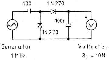
RF detector with 2x 1N270.
LA7MI Stein Torp made some measurements of a voltage doubler with
2x 1N270 on HF:
| RF (RMS) 1MHz | Detected DC | RF (RMS) | Detected (DC) |
| 10V 5v 2v |
28V 14v 5.4V |
100mV 50mV 20mV |
187mV 50mV 13.7mV |
| 1v 0.5v 0.2v |
2.6 1.25 0.45 |
10mV 5mV 2mV |
3.4mV 0.85mV 0.137mV |
DC output from a voltage
doubler with varying RF voltages (LA7MI, Amatör
Radio 1985-11 pg 299),
note that detected voltage may decrease for higher frequencies,
but not so much below 100MHz.
He constructed a quasi-compensating amplifier with CA3140E so
that the reading was within 20% accuracy. It is described on one
of my pages, but I am not capable of finding it now. It may also
be mentioned on page m2 as
"LA7MI LF/HF/VHF/UHF mV-meter". Some other possible
diode types are OA95, AA118, AA119, AAZ15.
If output voltage is not critical, you just want to see some DC
change as RF voltage varies, see sensitive RF detector using
silicon diodes (1N4148) on page m2
The problem with the detector is that it must have very high
impedance, the characteristique must be predictable, and the
performance must be checked and calibrated. A problem with
germanium diodes is internal capacitance, so they should be
applied with an RF-voltage-divider, a suggestion is shown here.
#1.10) Measuring small coil values
It is often difficult to measure small coil values, this
construction works fine down below 20 nanoHenry. The secret in
measuring such small values is to add a 0.5-1µH coil in series
with the coil under test. This extra coil should have high as
practical Q-value (dependent on you desires). Q-measurements may
not be accurate, but you can measure coil vales down to zero.
See also the notes and modification for Radiometer MM1f which
uses the principle mentioned with the extra series coil.
#1.11) Another RF
transformer construction for Q-meter
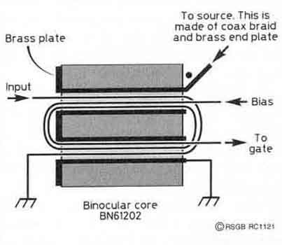
Another suggestion is to use an RF-transformer described by W4ZCB
for another purpose (ref. 3): To minimise leakage inductance, the
single turn braid must use brass end plates so the braid can be
opened up and pushed into contact with the sides of the hole in
the binocular core.
However, reasonable results can be obtained with just the braided
with enamel inside and no end plates.
References:
1) Zwischen-Basis amplifier with J308 2) G3SBI Radcom TT Dec 95
pp70-71
2) Zwischen-Basis cascode-amp. with J310 1) G3SBI Radcom TT May
95 pp60
3) Zwischenbasis amplifier W4ZCB and G3SBI Radcom TT Sept 96
pp70-71
4) Zwischen-Basis JFET amplifier 4) G3SBI Radcom TT Sep 98 pp
58-59
See the original notes on page Page r22
(2003.08.06)
#1.12) Edge-mounted p.c.b. tool
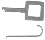
Some useful tool to pull out PCB's with edge-contacts. The shape
varies for different manufacturers of
telecommunication equipment
page-994 List of contents

2004.07.01