m11. Grid-dip-meters + xtal tester
m1.
LC and Q-meters
m2. RF
detectors, level meters, attenuators, dummy loads, signal
dividers
m3. RF
signal- and power generators
m12 Power-
and VSWR-meters
m21
Norwegian instruments
m22.
Old measuring instruments
m23.
Signal-to-noise-meter
m31.
LF/Audio instruments
#11.1: Philips professional GM3121 Grid dip meter
Philips GM 3121 Grid Dip Meter.
Note the Type 4662 indicator valve, this is a very old
neon indicator which was used as magic eye in some receivers
of the mid 30's, the length of the light depends on the voltage
across it, but I suppose it wasn't so useful in the
30's when valves when expensive, wages low, and dual types were
even more expensive, but later and in particular
when war surplus were overwhelming, prices low and wages higher,
it was no reason for not choosing a 12AT7,
6BQ7A or ECC85, so the optimum ideas have really changed, but
this circuit is still very rare construction.
GDM data sheet
Philips type 4662 neon indicator
tube is a strange type of indicator tube, probably
designed around 1935 for signal strength indication in broadcast
receivers, but seem to have been used very little for this
purpose, only one receiver has been found where this indicator
was used. But it works ufb for the GDM..
It is easy to find data for it in Frank Philipse's
tube database, but the link has changed, so I won't put it here.
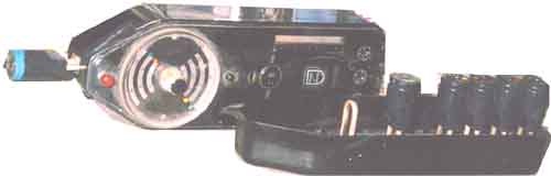
#11.2)Tech TE-15 GDM
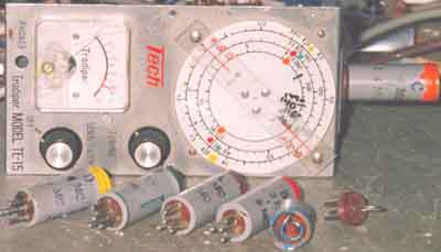
You may notice that the 2m coil is opened and modified. It also
another 2m coil,
but they cover almost the same range. Also note that all coils
and segments of
scale are colour-coded, using the normal colour
code: brown-red-orange-yellow-green-blue
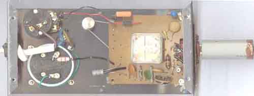
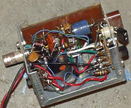
Inside view. Have removed some of the
rubbish which wouldn't operate properly, and gounded the
so-called "negative side" so that it will work on +12V
without shortcircuiting against other chassises.
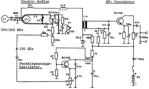
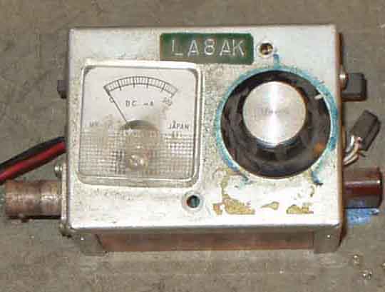
Tech TE-15 Dipmeter (Tradipper).
The instrument was purchased from Schünemann in Berlin in 1967,
and have been in use regularly since. One problem was
that it uses 9V battery, and it was usually flat when you need
it. So I connected it to external 12V supply, but the problem is
that it has plus to
chassis, and every time the chassis touches other equipment you
the wellknown SHORT-CIRCUIT between dipmeter chassis and grounded
chassis state occurs. So I decided to convert it to positve
supply voltage. The new circuit diagram is shown. As the
oscillator frequency isn't
particularly stable and clean, I wasn't too interested in the
monitor function, it wasn't found particularly useful at all.
OC45 (455kHz IF amplifier
transistor) is experienced to be one of the best DC-amplifier
transistors for low input voltage, better than the audio
amplifier type used in the
original griddipmeter and was therefore used to improve the
meter.
One problem is on the highest range, it simply
won't operate properly. The reason was found to be the coil, it
is not really a coil, but a short
between two pins inside the connector. Remove the short, and wind
a coil using 18SWG copper wire, 5turn with 8mm diameter - not
critical -
it will cover 2m and above it, slightly lower frequency range
than it was earlier, but it works as DIPMETER, and you may now
dip your 2m coils.
I also have the Philips GM-3121 griddipmeter, it is somewhat
better than TE15, and must be used with care since the ECC85
exites higher
RF level, but I must admit, it is other, better ways to measure
coils, but GDM provides an easy way to check resonnances and
signals in tuned circuits.
#11.3:
Alternative modern version to the GDM
When you already have a modest signal generator (preferably not
thumbweel tuned), but miss a reliable griddipmeter, this may be
something to
consider. Tom (LB8X) says that MFJ259 will work fine using the
described principle, and you need not buy adapter to try (see
next figure).
It is not a GDO, GDM or transistor-dipmeter or such, it is an
alternative.
The notes below are based on ideas described in an article, see QST May '86 pp.14-20: W7ZOI Hayward
"Simplified Scalar Network Analyzer"
p.14 (Feedback Aug p.40), with the subtitle:
Beyond the dipper (using signal
generator)
here is shown my version - tested up above 200MHz,
frequency limits are somewhat odd to discuss, it really depends
on making inductive coupling to a tuned element, and change the
shape to fit for different purposes. For UHF strip-lines one side
of the probe should be flat for maximum coupling, while on LF -
using 88mH toroids it is not difficult to make a 1-2 turns link
into the toroid, but it is worse to use with clock cores.
#11.4) Another alternative GDM
Dip-meter using signal generator, this is a
simpler version of the W7ZOI type dipper, in function is similar
to using MFJ259 withthe set of test coils described in the
previous notes. It seems important to use a signal generator with
large range variation, HP-651B has 10:1 ranges, it is not stable
and accurate enough for receiver tests, but very suitable here,
toggle-switch tuned generator is hopeles device, you will tune so
slow that you won't be able to see the dip
#11.5)
Single capacitor type GDM
LA7MI dipmeter with single capacitor and coil without tapping (AR
pg305 nov 82)
Other means of GDM's to consider (DUBUS VHF UHF Technik Vol.1
1980)
UHF-Dipmeter
.................................................DL7QY pg.350-355
VHF-UHF Resonance Meter by DJ2HF and DC0DA pg 355-358
Superregenerative UHF Dipmeter................. DL7HG pg. 339-341
#11.6) UHF
Dipmeter (DL7QY)
The construction is 25-30 years old and some changes are evident,
but still some good ideas could be
seen.
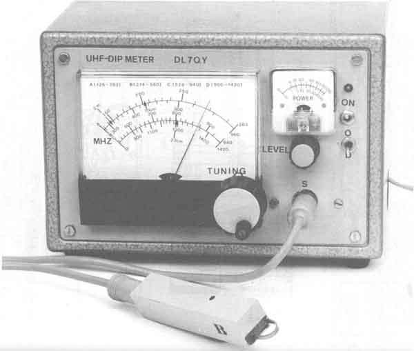
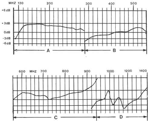
This dipper is working well in the range of 130-1400MHz. The high
sensitivity enables the user to dip small strip line circuits
with good reliability. This is achieved by using for different
probes, each containing the whole RF circuitry expecially
designed for the corresponding frequency range. The tuning of the
oscillator is done with variable capacitance diodes. The tuning
voltage is controlled by means of a good potmeter (fig.1), and
indicated by a large panel instrument which can be calibrated for
frequency directly.
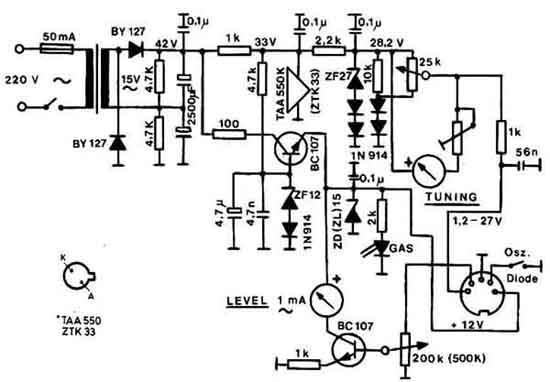
Power supply for DL7QY UHF dipmeter
Two stabilized voltages are needed, +12V for oscillator and level
amplifier, and +30v for varicap tuning. Here is used a 15V line
transformer with voltage doubler, followed by two regulator
circuits - as shown in fig.1. The tuning voltage is stabilized
twice by parallel regulators; IC TAA550K and a zener diode ZF27,
which is temperature compensated by two 1N4148 (1N914) type
diodes in series.
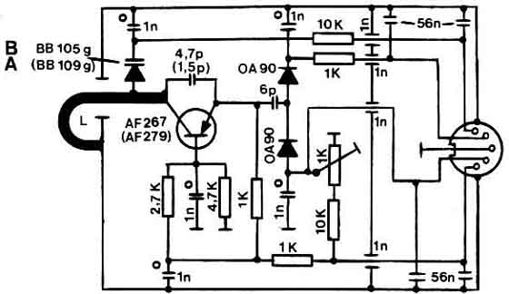
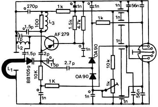
Dip-meter RF circuits and level
indication:
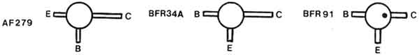
All four probes have oscillator transistors in grounded base
configuration, fig 1b shows the connection schemes of the
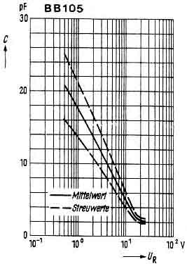
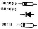
recommended semiconductors. The varicaps are of type BB109, BB105
and BB141. They have low dissipation in the UHF range. Fig 1c
shows their capacity variation due to tiuning voltage changing.
The oscillator RF voltage is rectified in a voltage doubling
circuit in each probe, and amplified and indicated by the remote
"Level Indication" meter in the power supply box (fig
1). The rectifier diodes are biased with an adjustable voltage.
It is adjusted to that voltage, at which the meter needle begins
to rise from zero (when transistor is not oscillating - finger
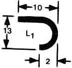
across the U-shaped quarterwave strip-line inductor).
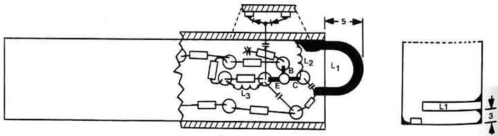
The probes are connected to the power supply unit by a shielded
5-wire cable, using stereo pick-up connectors. The probe boxes
are made of tinned iron plate 1mm thick, with outlines of 100 x
20 x 20mm. It is convenient to prepare at first long sheet strips
20mm wide and then cut off the desired lengths. The parts can be
soldered together easily.
 |
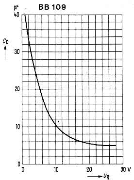 |
BB105 and BB109 varicap tuning diode capacitance
(suppose these diodes are rather old now)
 |
 |
Connexions for the semiconductors
AF279, BFR34, BFR91 (Isn't BF479, BF679 or BF979 some more
commonly found PNP devices?)
Oscillator levels for the different ranges
 |
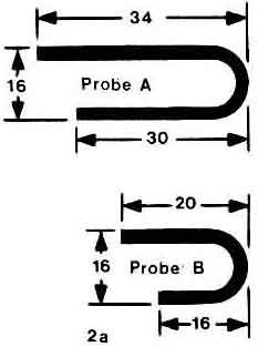 |
GDM Probe A (130-280MHz)
GDM Probe B (270-560MHz)
 |
 |
GDM Probe C (530-940MHz)
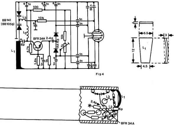
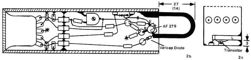
GDM Probe D. 900-1420MHz (DL7QY).
At this range oscillating was achieved with an npn silicon
tranistor of the type BFR34A. Ft=4GHz.
Two varicaps BB141 connected in series tunes the frequency from
1420 down to about 800MHz. Because of the low L/C ratio, good
sentitivity is fround from 900MHz and up. The lower part will not
be used. Some spurious resonnances with flat peaks occur around
1100MHz. In this range dipping is possible, when the level
indication will be recontrolled by turning the potmeter
"selectivity". Fig.4a shows the outlines of L1. It is
bended to shallow bow out of the probe case to improve the
coupling. The front view (fig 4b) shows the arrangement of the
two variacaps beneath L1. Their proper sites, especially the
nearer the varicaps will be placed to L1, the higher the upper
frequency will go.
11.7. Superregenerative
UHF-Dip-meter (DL7HG)
Superregenerative UHF Dipmeter (DL7HG)
DUBUS VHF UHF Technik (Handbook) Vol.1 1980 pg. 339-341
see more VHF/UHF/SHF techniques on page D.
11.9 Xtaltesters
 |
 |
My old xtal tester, built in 1970, and modified several times.
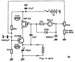
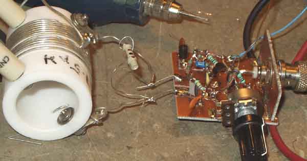
11.10) Simple xtal tester which works with
a frequency counter. Somewhat more open possibilities for making
experiments.
Connect a VOM (preferably an anague type or 100µA-meter with
series resistor) to the testpoint may indicate the crystal
activity.
It is almost difficult to find a transistor which won't work. It
is a good idea to mount some different xtal sockets on a box.
The variable capacitor is measured to 10-30pF.Most NPN general
purpose transistors will operate (suppose the only transistor
type
which doesn't work is 2N3704)
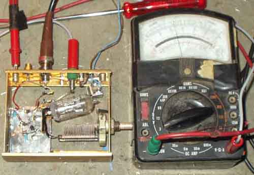
The xtal tester checking if it works with 307kHz xtal - although
the optimum component values are for 3-15MHz
11.11) The xtal tester as VXO
(variable crystal oscillator)
It was interesting to see how much swing I could get with
some representative selection of xtals for considering some VXO
circuit. The table below is only meant to show the comparison
between xtals on different frequencies and overtone xtals
operated on fundamental frequency. It is no secret that larger
tuning range could have been achieved with some xtals, but that
is another story, the comparation was more interesting for my
application. In the first instance I am planning a close-in
frequency sweep-oscillator to analyse ultimate selectivity of
receiver's IF filters.
The 10-30pF tuning capacitor is certainly not optimum, so some
larger range might be possible for several xtals, and the
capacitors on the transistor could be optimized, too.
If you try to make the tuning range large, the output level may
vary a lot, and it may become a problem to limit the output
voltage. Too hard limiting may worsen the noise sidebands,
| Frequency | F min | max | deviation | notes |
| 3686.4 | 3686.14 | 3687.76 | 1.62 kHz | HC18 |
| 9216 | 9214.80 | 9221.43 | 6.63 | |
| 11981.35 | 11983.62 | 11993.29 | 9.67kHz | |
| 26786 | 8927.97 | 8935.33 | 7.36 | HC18, R/C |
| 27005 | 9000.60 | 9007.80 | 7.2 | HC25, C/B |
| 37800 | 12594.66 | 12604.51 | 9.85 | HC18, R/C |
| 14318 | 14318 | 14328 | 10kc | Computer |
| 15700 | 15697.50 | 15707.80 | 10.3kc | AP22 |
| 46.3 | 15417.93 | 15430,6 | 12.67kc | overtone |
| 13352.080 | 13350.07 | 13360.54 | 10.47 | Storno CQM |
| 10700 | 10746.88 | 10755.67 | 8.79 | Trio, HC6U |
| 11541.34 | 11538.92 | 11549.23 | 10.31 | HC6U, 30pF |
| 14 866.0 | 14 864.54 | 14 874.37 | 9.83 | AP22 |
| 15 539.30 | 15 537.12 | 15 546.11 | 8.99 | AP22 |
Improved variable xtal oscillator (VXO)
Resonance tester.
A sometimes useful instrument, when it is not possible to dip a
tuned circuit, it may be placed in a screened can.
Problem is that it doesn't always work, perhaps it is room for
improvement here. It is neccessary to have DC-
return via the coil to instrument ground. In some cases an RFC
could do this, but often it would upset the measurement.
connections for some actual transistors
It seems problem with definite dc level on the second transistor,
and excitation control for the first stage, so it seems after few
tests that this could be a solution. It doesn't pull the
frequency down much compared to the dip-meter frequency. A later
version using BF245B, BF324 (PNP) and BF314 (NPN), the two latter
semiconductors has same pin connection as for BC547/BC557, in
spite of what data sheets may tell! Wished to use some definite
RF devices, but if they are difficult to find, replacement for
BF324 is 2N3906 (=BC557 and BC558), and for BF314 is 2N3904 (=
BC547, BC238), MPS918 or BF199 types are better NPN devices.
The last version (minus one). The coil shown has very high Q, it
is the tank coil from Heathkit HX-20
 e/m
e/m
Last update: 2005.01.08