Noise measuring equipment
Noise measuring equipment
m1.
LC and Q-meters
m2. RF
detectors, level meters, attenuators, dummy loads, signal
dividers
m3. RF
signal- and power generators
m11 Grid
dip meters
m12
Power- and VSWR-meters
m21
Norwegian instruments
m22.
Old measuring instruments
m23.
Signal-to-noise-meter
 |
 |
White Noise generator (I) for HF receiver
selectivity checks
Noise level measured into 75ohm 3.1kHz BW using Siemens D2006
level meter: -80dBU (77.5mV)
from zero to 1MHz and drops 3dB on 17MHz. Decrease the first
coupling capacitor (68nF) to 10nF
to increase the lower limit to 50kHz. The amplifier is copied
from one of LA7MI's constructions,
combined with a general audio amplifier. A noise level was needed
to test vintage receivers and
requirement was not beyond 10MHz, but it seems that some further
bandlimiting circuit could well be
used, particularly since I am not interested in noise spectre
below 200kHz.
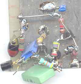
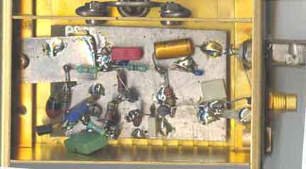
Picture: Zenerdiode connected (E-B junction)
MPS918 at left side and the other devices follow as
on the circuit diagram. The component values were first
calculated, but I used the components which
was closest, but it seems to cause no problem because of the
heavy DC feedback. Reducing first
emitter resistor (from 47 to 22W) to
the half value will increases the output by 3dB on the lowest
frequencies.
 |
 |
White Noise generator with MSA0304 booster
amplifier. The picture shows the 1st
version noise generator which has -68dBU 75 ohm o/p (3.1kHz BW),
while the 2nd
has -66dBU (rel.0.775V).
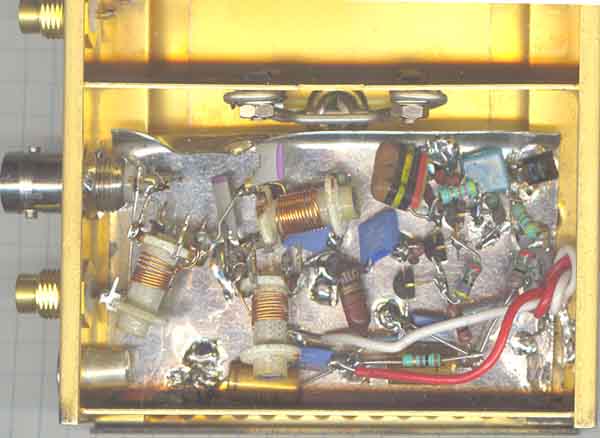
White noise generator II.
The 2nd version built on tinned iron plate, output is measured
using Siemens D2006 selective level
meter to -66dBU 75W (3.1kHz BW), and
30mV into 50W using LA7MI broadband
voltmeter
(described further down this page). Suppose this is quite high
level and I am not sure if it is worth
increasing it further since the main task is to check surplus
receivers. Level on 10MHz has dropped
by 2dB.
The noise generators were housed in NERA surplus boxes, and the
2nd room is not used.
Have kept the conhex connectors since they are free and available
in very large quantities as well as
different cablelengths with connectors.
It is some some minor changes of components for the two different
versions. It increases the gain by 3dB,
without any noticable change of frequency response, but the only
measurable difference is that the version
has 3dB, so it seems no problem to copy the circuits, the only
importance is to choose a device with 6v e-b
breakdown voltage. The box measures 100x80x30mm
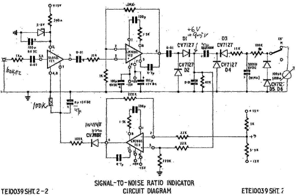
Signal-to-noise ratio meter (indicator), circuit
diagram [anno 1972]
100kHz input e.g. Racal RA17 or similar receiver. Measures degree
of noise-modulation on a carrier and feed it
through a logarithmic detector. Could possibly be made using more
advanced technique.....
Stein Torp LA7MI instrument with notch filter on 10MHz to measure
oscillator phase noise. Sorry, the text is not available now.
Reference: Eugen Berberich DL8ZX. "Quarz-Notchfilter für
Oszillatorrausch- und Intermodulationsmessungen im
UKW-Bereich."
[Scriptum der Vorträge, 40. Weinheimer UKW-Tagung 16./17.
September 1995 (DARC OV Weinheim), Seite 10 ...17]
Dubus Technik VI (year 2004). Leif Aasbrink, SM5BSZ. Receiver
Dynamic Range, Part 7, pg 356. Crystal Notchfilters [but we do
not understand why he doesn't use trimmer capacitors in series
with the xtal and avoids buying several douzen xtals]
Noise Figure calculation table
Noise figure calculation chart to calculate the overall
improvement when you change the input stage
NF or gain in a receiver (will print better than it looks on the
screen).
pg-994 index for technical
topics
 e/m
e/m
Last update: 2004.09.23