
M2 RF detectors, level meters, attenuators,
RF termination (dummy loads),signal dividers
 m1. LC- and Q-meters
 m3. RF signal and
power generators
m3. RF signal and
power generators
m11. Griddipmeters
and xtal testers
m12. RF power- and
VSWR-meters
m21 Norwegian
instruments
m22. Old measuring
instruments
m23.
Signal-to-noise-meter
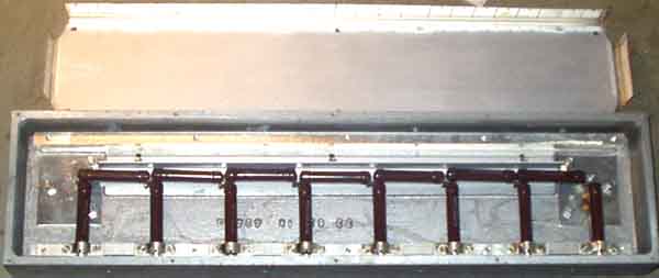
#2.1) Surplus attenuators
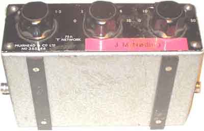
Muirhead & Co No. 355748, it has 0-61.5dB in 0.5dB steps (75
ohm).
Problem with attenuators is that when you need them, you can't
find sufficient amount of them. I've often needed 3 for some
experiments, and 75ohm attenuators in a 50 ohm system does not
cause much inaccuracies, so when you have checked it and are
aware of the possible problems you just don't care so much.
Another argument is that I use a lot of available cables and
equipment from work which are made for 75ohm systems, and it
saves me a lot of trouble to use what is around instead of buying
what you really don't need.
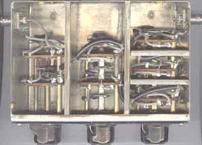
Inside look of the Muirhead 75W
attenuator (boatanchor). It is well screened between the
sections, but isn't much looking like an instrument for VHF, on
the other hand it seems to be good - at least for the lower part
of VHF range. It came with some Marelli radio link equipment and
I had to change the connectors to BNC. Have passed some to other
amateur radio experimenter and they are quite satisfied with
using them for 50W. But again you need
to be an electronics engineer - with 30 years experience to
understand how easy it is!
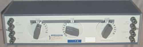
#2.2) Telonic Model TG-975 (First owner: Tandbergs
Radiofabrikk, year: 1965)
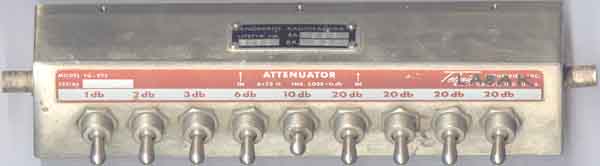 |
 |
Another 75W (0-102dB) attenuator I bought in 1980 because it looks so easy to repair. Has used it on VHF and 70cm (50W), when you are aware of it it is only marginal difference between a 50ohm and 75ohm instrument. The switches are mounted between the different rooms with the resistor through holes.
#2.3) Danbridge Decade Attenuator type DA3HS/D; 600W, 0-111dB in 0.1dB
steps.
Decade resistors and decade attenuators are among those
items I regard as waste or time and money, but I got it from
work, and have never used it, or missed it. Such things are
usually believed to have a value by persons who don't understand
much. I wouldn't use a decade restance unit to find a resistor
value! This unit is better for next junk-sale.
(S.: atenaters)
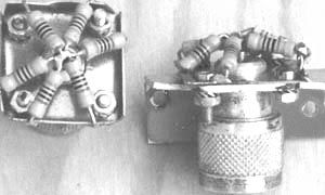
#2.4) Practical VHF/UHF
Dummyload to build
 |
 |
Building termination with standard
components is easier than people think!
But, usually experience is better than thinking.
Practical dummy-loads mounted on N-connectors. Using male
connector it can be connected directly on the Bird Model 43 wattmeter. it uses 6x 300W
1W Draloric LCA0414 carbon resistors. To ease soldering a timmed
iron plate is attached to the connector first.
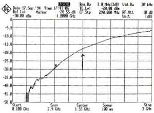
The Rohde&Schwartz team offered to measure it
at a their stand at the Weinheim UKW Tagung, the one with male connector has almost 20dB
return loss at 1300MHz, - not bad for standard type
carbon resistors! Only
had one available.
#2.5) Power
Attenuator (25W 30dB)
 |
 |
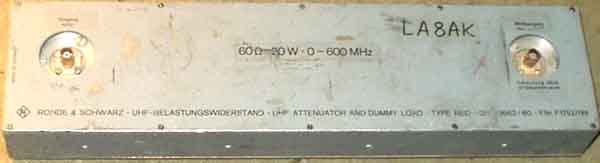
Rohde&Schwarts RBD 600MHz
30dB attenuator uses discrete power resistors, note the frequency
limit, it is professional equipment! The attenuator is original
60 ohm, so I have modified it with some extra resistors to 50
ohm. The original Dezi-fix connectors were easily changed to BNC.
#2.6)
more power attenuators
Some power attenuators used for experiments on HF
High-level PIN-diode
attenuators, see page c11
#2.7 RF
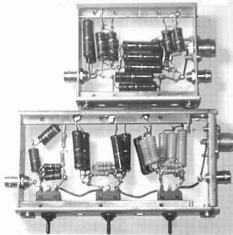
Level meter using Philips TDA1576
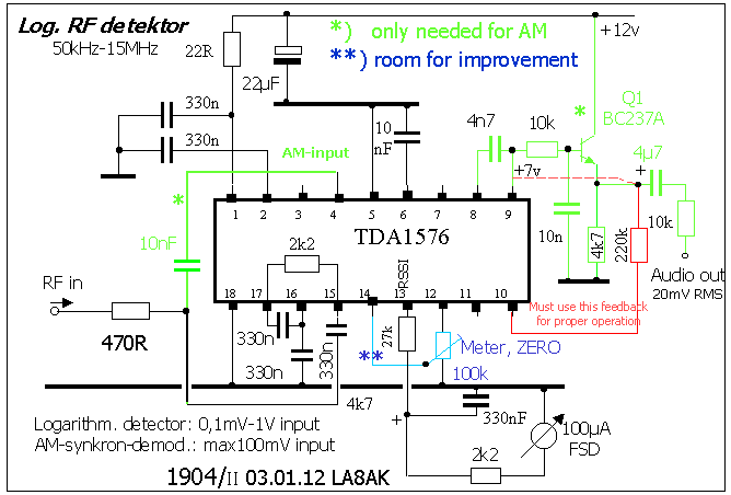
10a) TDA1576 (Philips) as level meter, has 70dB range. But using
the internal meter offset adjustment circuit upset the range, so
it seems better to use an outside circuit. Also useful as
quasi-synchronous quadrature AM-demodulator, but it is overloaded
with larger than 100mV input.
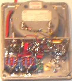
Bird's nest using TDA1576 as a general purpose detector for
10kHz-15MHz
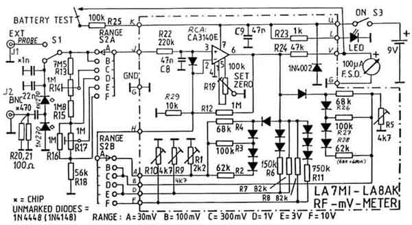
#2.8 LA7MI linear scale
RF-mV meter for 0.01-1500MHz.
Believe it measured better than 10% accuracy to a linear scale on
all ranges except the lowest (30mV) up to 500MHz. It was not
intended to by LA7MI to have this range since strong transmitters
in the neighbourhood gave over 30mV deflection with the high
impedance probe, but I added it in my version since I mainly
measure 50 ohm circuits via coax cable, and only very seldom use
a high impedance probe. Also used it with small coax loop to
align local osc for 2320MHz transverter.
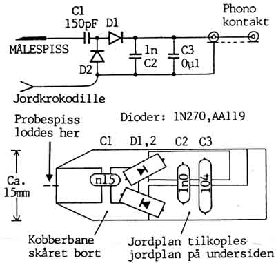
RF probe for RF mV-meter. Ground on two-sided
PCB laminate component side is connected to the screen side
below.
The board patterns is fabricated using hacksaw. The construction
is so self evident that I believe you don't need to have the
words translated, it was only a point in the first amateur radio
magazine it was presented, and as such not shown in DUBUS.
jordplan=groundplane, probespiss loddes her =probe tip soldered
here, jordkrokodille = crocodile clip to ground.
See also the other alternative instrument described below.
 |
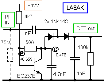 |
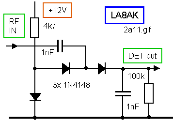
#2.9)
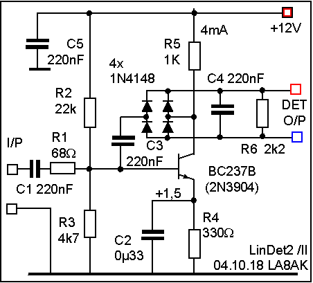
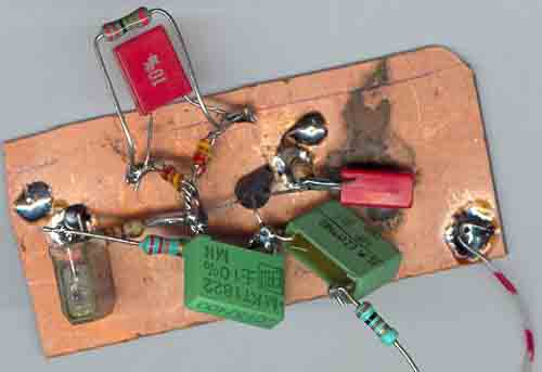
RF detectors using 1N4148 type silicon diodes.
An extra diode is used to forward bias the detector. It has
relatively low impedance and decoupling is not usually necessary.
Using a transistor instead of the diode it is easier to optimize
the forward bias voltage, but the voltage drop over the diode is
current dependent, and still with 250mV forward drop it draws
some current. Another problem is temperature stability.
| Supply voltage | Base voltage | Collector voltage | DC output voltage |
| 9v | 643 | 518mV | 44 |
| 12v | 659 | 476 | 34 |
| 15v | 649mV | 438mV | 26 |
It is important that the supply voltage is stable
to use the circuit shown above
| RF input (450kHz) RMS | Detector output (2nd circuit) |
| -- | +30mV |
| 25mV | +33mV |
| 80mV | +58mV |
| 250mV | +300mV |
| 400mV | +625mV |
| 800mV | 1.568V |
The detector is not linear, but may be useful for
several non-accurate purposes
#2.10)
Very old LF selective level meter
(Messkoffer)
TEKADE Träger-Frequenz
Meßkoffer 5-155kHz (later German term is Selektiver Pegelmesser), Suppose this is
the first selective voltmeter ever made. They were used to
measure levels on multi-channel carrier frequency systems. One
such instrument were placed in Kristiansand, another in Arendal
since it was subsea coaxial cables to Denmark, believe it was 8
or 15-channel systems (ME8 & MG15) during the war and many
years after. See Die deutschen
Funknachrichtenanlagen Band2 "Der Zweite
Weltkrieg" pg139
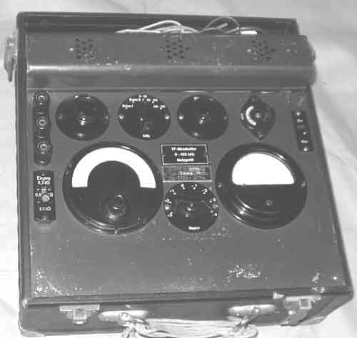
See chapter M22 for more info
about old instruments.
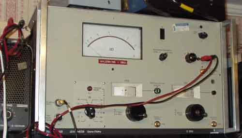
#2.11)
Siemens D2006 Selective
level meter (Selektiver Pegelmesser)
The advantage with this instrument is that it is still easy to
repair and modify.
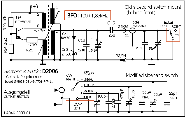
Sidetone modification.
The problem with many of those Selective Level meters is that the
pitch is meant for somebody else, but not hams.
It is far too high for CW reception, for this unit it is 1.5kHz
(some other instruments may have 1850Hz). So you cannot use the
lowest bandwidth to listen to a CW station, only for
measurements, and must tune to lower pitch using wider bandwidth.
When I listened to SAQ on 17.2kHz (Alexandersson Generator) last
summer, the signal to noise was only 6dB or less, but I later
discovered that it was some strong noise sources
just above this frequency, and if I could use the 80Hz bandwidth
it would improve 30dB. It was therefore a good idea to open the
handbook and start interpreting the German text. Soon it was
discovered the solution here is quite simple, all the
modifications are made behind the front plate, none on the actual
board, you remove some components and install a swith with at
least 4 posititions and a small board for trimmer capacitors with
some fixed values in parallel. It was difficult - even when
reading the book, to understand the proper way to open the
instrument. Was it neccessary to take off
the front? Yes, it was, and it seemed rather difficult
first, but wasn't so difficult, when you learned about it, and I
needed to remove it later, because I forgot some screws.....
The board S45035-D5142-..(Ausgangsteil) has a
simple product detector and BFO. The BFO frequency is tuned with
2250pF and it is shifted by S4, possibly shifting it 1.85 below
and above 100kHz as the switch is set to left or right. when the
250pF is grounded it is LOW and when it has the external
capacitors in series it is HIGH. The unmarked capacitors above
the switch behind the front are 25pF styroflex and 25pf air
trimmer, I measured 41pF, but don't always rely on the
instrument, and to this figure you must add some 50pF for the
PTFE-cable.
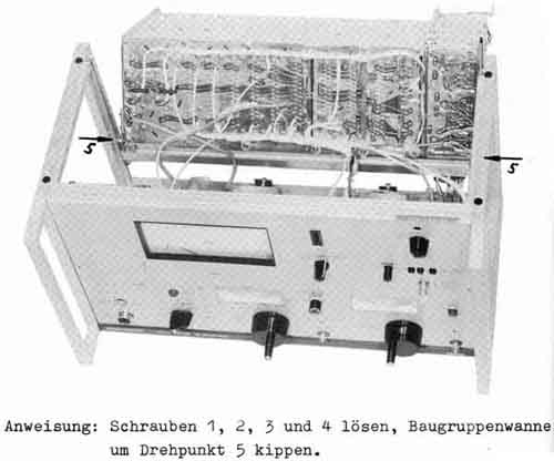
Remove all plates and screws and when you still can't find a way
to get into the box, you must start reading
the instruction book, Chapter 4,
MAINTENANCE - only to discover that
you can just as well put back some of the screws again and remove
the upper unbrako type screws instead - to slide the upper unit
backwards. It was a fight to remove the front plate, but it went
after all. Careful with all those terribly small 2.5mm screws,
nuts and washers!
Considered using varicap diode (BB112 or BB130), but it must be
shorted for USB, it demanded a potmeter with an Normally-Open-switch and
they are rare, so I decided use a switch with 4 positions
instead.
Connected 3 trimmers and fixed value capacitors on a bracket with
pcb laminate where the old capacitors had been.
The 4 positions are now:
1. Shorted coax cable as earlier CCW with 1850Hz pitch for 80Hz
filter.
2. 470pf+270pf + 100pf trimmer - to tune one sideband with
500-800Hz pitch
3. 56pf + 100pF trimmer, to tune the opposite sideband with
500-800Hz pitch
4. 22pF + 20pf trimmer (or 10pf fixed and 40pf trimmer) for CW as
before
used a six position switch, but couldn't think of the need to use
more than 4 positions, didn't find any small swiches with long
shaft, so the nut must protrude through the front plate, so the
hole must be widened a little for the nut.
The audio output level is high enought to drive a 300ohm dynamic
phone inset (+1dBm or 700mV)
Servicing Siemens D2006 Level Meter, when you have unscrewed the
proper screws amongst the many which seem much more likely to
choose...
#2.12)
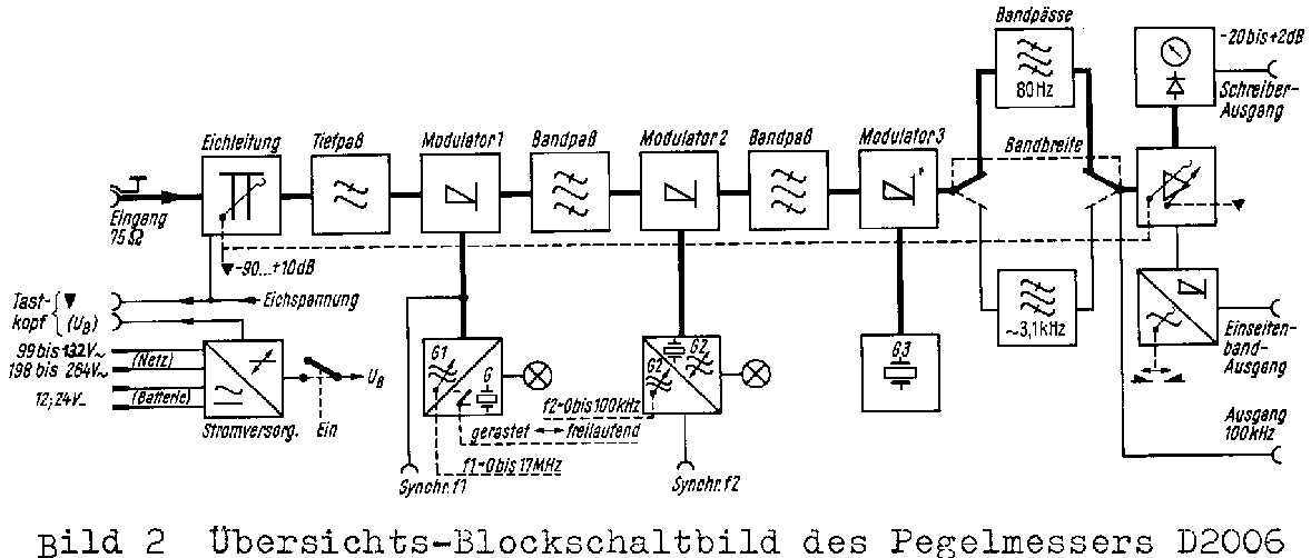
Siemens D2006 Level Meter.
Block circuit
#2.13)
Active hi-Z RF probe for use with D2006 or
other instrument
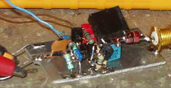
The probe under check connected to Siemens D2006 selective level
meter (or other similar instrument)
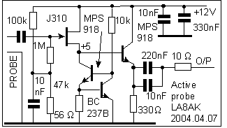
Circuit diagram for the probe. 1dB variation 50kHz-18MHz using
Siemens D2006 Level meter (75 ohm), probe voltage loss: ca 1.5dB.
The input coupling-capacitor is 100pF.
An alternative is the Maxim MAX4005 with frequency
limit of 950MHz, but I needed the circuit today and don't want to
wait for something I am not really sure if could find or
how long it takes to get it. This device requires
+/-5V supply.
>.905. see
block diagram for D2006 Pegelmesser (too large to display on this
page)
#2.14)
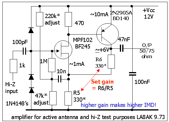
General purpose high input impedance amplifier
was designed by LA7MI in 1973 for use as active antenna. It is
important not to use more gain than neccessary, also the positive
feedback to the input, should be done with care, and avoided if
not definitively neccessary. We used it for a while, but I had
some intermodulation problems with a local BC-station, it was
later used with a general coverage frame antenna covering
0.5-4MHz without any problems. It is a simple circuit for some
test purposes
#2.15)
Linear RF detector
I've wondered what is the important rules to make a linear
detector with conventional technique and germanium diodes It is
described in Wandel&Goltermann SPM-3. The upper transistor
operates as constant current source and at the same time balances
the collector voltage for the first stage.
RF detector used in SPM-3 (Selektiver Pegelmesser)
 |
 |
SPM-3 (Wandel&Goltermann) is
probably one of the most popular portable "Selektiver
Pegelmesser/Selective Level Meter", it covers 0.5-612kHz and
it is ideal for 136kHz measurements, it has built in chargeable
batteries for portable operation (but they are most likely
defective).
It is a matching signal generator - PS-3 - which may be
controlled by SPM-3 for tracking on the same frequency.
#2.16)
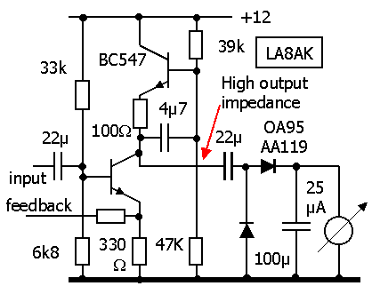
RF detector.
This is based on techniques found in HP-651B, but increasing the
current through 2N3866 (BFR96) to 20mA LA7MI discovered that the
frequency limit increases, -3dB limit was measured to 70MHz, it
was used in his broadband RF millivoltmeter, constructed in
November 72 - covering 360Hz-36MHx with 0.7dB variations. I is of
course an old design, but sometimes once may still find such
circuits useful, it is several other devices which simplifies
operation like NE/SA604/614, TDA1576 etc.
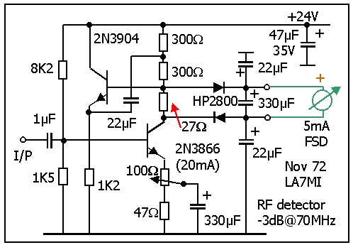
HP651B detector circuit
#2.17)
 |
 |
Another linear detector which isn't so critical
for matched diodes, almost any smallsignal silicon diodes may
work has been tested in the range 50-5000kHz,
but I am not quite certain about all the critical factors.
| Level. | -10dBm | -20dBm |
| 50kHz | 2.0 | 0.608V |
| 190 | 2.05 | 0.654V |
| 300 | 2.05 | 0.657 |
| 490kc | 2.05V | 0.660 |
Measured with WG PS-3 and Fluke 8020B DVM
The detector may well be connected to a 1mA FSD 2kW meter
#2.18)
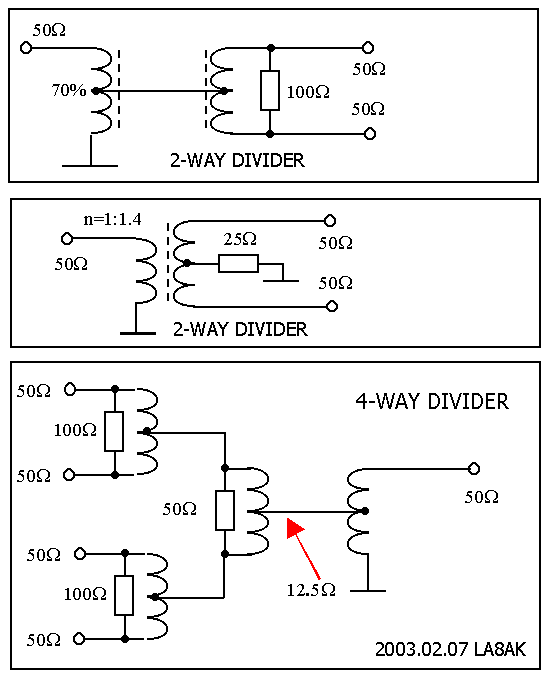
2-way divider (LA7MI)
#2.19)
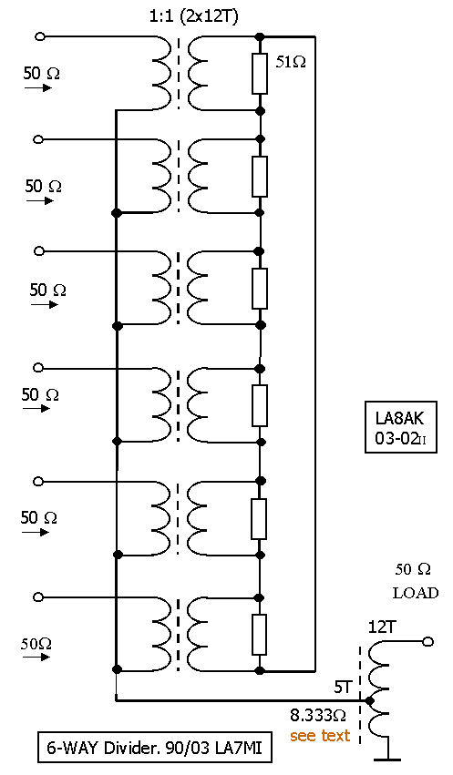
6-way divider (LA7MI)
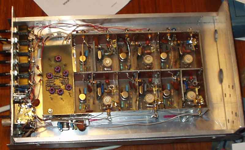
A practical application in a multi-frequency xtal
oscillator
Power dividers: See 32.
Weinheimer UKW Tagung, Scriptum der Vorträge 1987:
Leistungsteiler für VHF/SHF (DJ1EE):
1) Hybride Leistungstrafos, breitbandig KW-UHF
2) 3dB Richtkoppler (Koaxial bzw. Streifenleitungstechnik)
3) 3dB Branchkoppler (Planarer Streifenleitungstechnik)
4) Mehrwege- Wilkinsonteilr (Planare Streifenleitungstechnik)
Leistungsteiler/Addierer nach Wilkinson, Spannungsverstärkung
der Einzelverstärker,
Breitband-Wilkinsonteiler (144-432MHz)
Booster amplifiers, see page-L2
or c14
#2.20)
It was a problem to find 2m signal generator with sufficient
stability for ssb/cw 25 years ago, while an RF generator was
easier to get. Here is my up-converter using SBL1/SRA1. The
oscillator with 43.333Mhz xtal produces 130MHz to mix with 14MHz
from the generator, to give a signal on 144MHz. The mixer has 7dB
loss. To make it easy, I added attenuator on the input and output
for total 20dB lower level than the level generator has. To
convert from dBU (600 ohm reference level, 0.775V = 0dB) to dBm
(50W) you must add an attenuator of
10*log (R1/R2), where R1=600W. And if
the generator has 75ohm impedance you could use a
minimum-loss-pad.
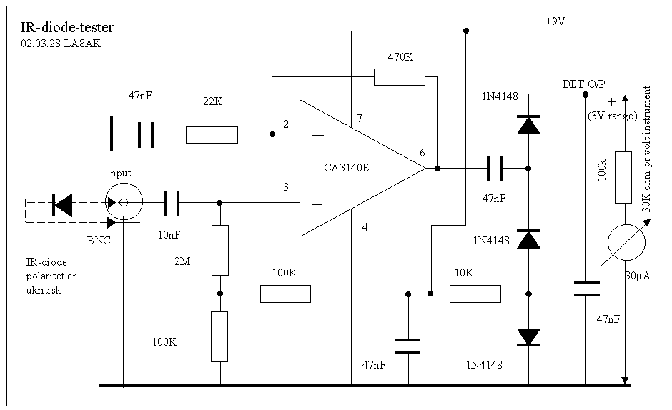
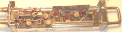
IR test receiver - to test
IR transmit diodes, any IR diode will work, I used a transmit
diode for
my receiver
#2.21)
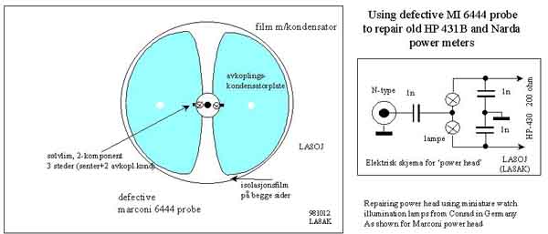
LA8OJ used defective MI SHF power meter heads to make his own
probes for NARDA microwattmeter using subminiature lamps
#2.22)
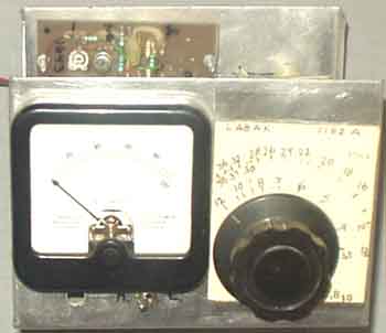
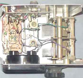
LA7MI 360Hz-36MHz broadband
level meter.
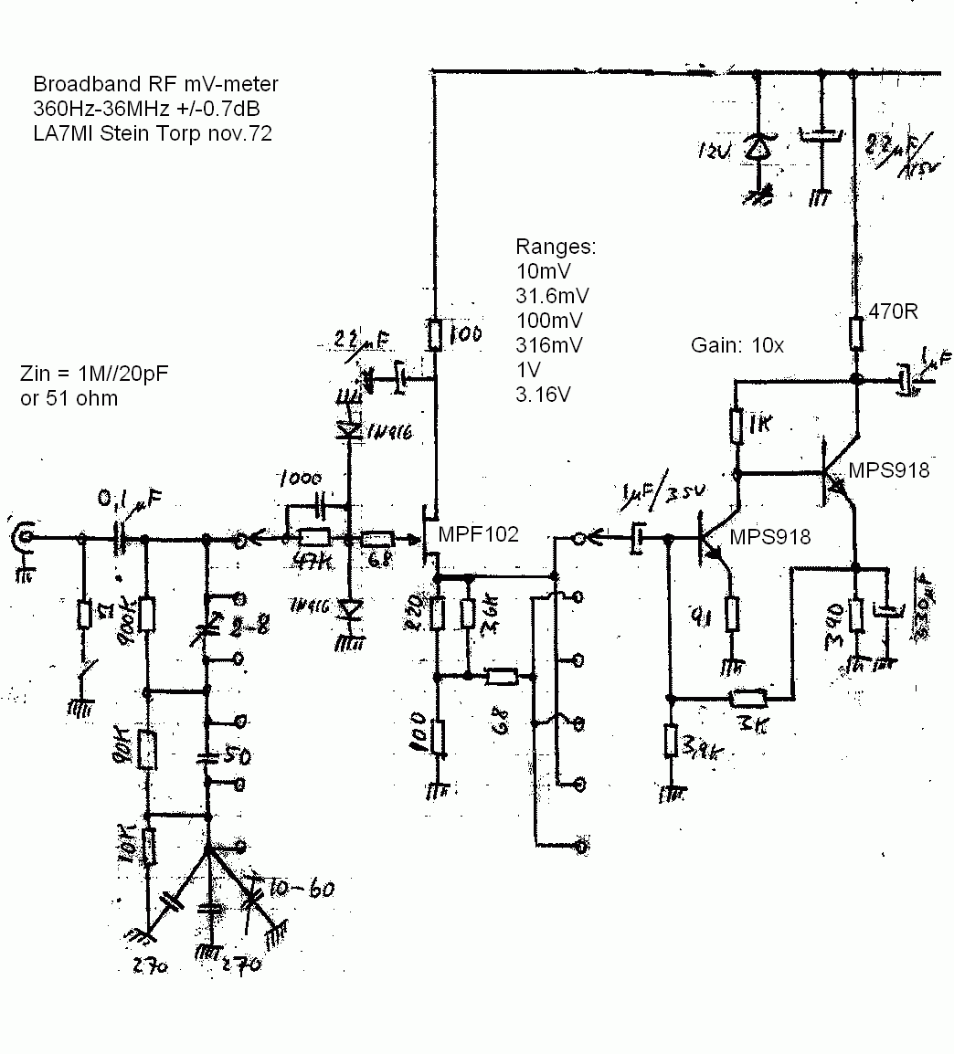
LA7MI linear broadband RF mV-meter (Circuit diagram Part 1)
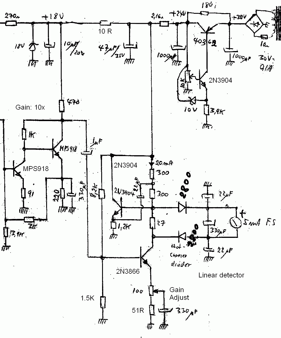
Part 2. Linear RF mV-meter
Some "Pegelmessers" have a selection for broadband,
this is useful for several measurements, but usually this is only
available for instruments covering up to 600kHz. Here is shown a
broadband level meter covering from audio to 36MHz, and with some
inaccuracies further up.
Many IC's are available for RF detectors, but they are not
linear. A linear instrument has apprx 20dB ranges, but 10dB
covers most of the scale.
Believe the circuit diagram of the RF detector was found in HP651
signal generator, but it was improved with higher current.
The rectifier delivers 30V DC
#2.23)
'Selective' RF level meter
 |
 |
"Selective" RF voltmeter for HF (two ranges) built in
1982 (described in Radcom)
N2PK's Amateur Radio Projects Page
Nolan
Lee's site for tube testers
Old instruments and tube testers,
see http://www.one-electron.com/FC_TestEquipment.html

Last update: 2004.10.18
