
 I
I
(Reflecties door LA8AK)
List of related pages:
 c. Amateur radio technik
c12 technical topics II
c13. Tecnical topics III
c21 QRP notes *** Note that some topics are moved to
this page ***
c42 Constant gain, variable
bandwidth xtal filter using negative resistance amplifier
c61. Components and store
c97 Techn. themes to discuss
(from G3VA's Technical topics)
g45 CW/RTTY/Hell demodulator technik
c51. TVI filters for HF and
VHF
Special theme:
g4. Power supply
topics
 |
 |
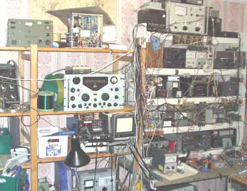 Main operational shack and lab. |
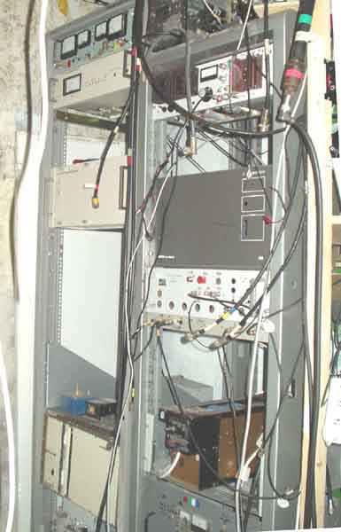 Remote VHF/UHF/SHF equipment |
1b) Audio oscillator using 88 or 77mH toroid coil (pupin
coil for telephone line). Just a reference circuit,
but one may sometimes need such; perhaps for another frequency.
It was made, based on experience
with 50kHz BFO for Drake 2-B, and later alternative BFO for R-4 -
CW-meteorscatter product detector
as plug-in unit on the rear of the receiver.
2a) Digital 90° phase shifter using D-type
flip-flops
4a) Low-noise XO for 12MHz,
based on an article by DJ2LR Ulrich Rohde in Ham Radio around
1976
Similar circuits have been applied in all my 2m/70cm/23cm beacons
since 1978.
5a) TBA120 as AM demodulator.
Equivalents are SN76660N (TI) and S041P
(the latter is a low power version). It is in fact a
CW/SSB/AM-multimode-detector, but the
BFO line is connected to the signal from the IF. Believe I tested
it in my Drake 2-B.
Please note that TBA120AS, TBA120S, TBA120C, TBA120D etc are
different and may not function
satisfactorily in this construction. It is also suggested the
change for use as SSB detector,
but it is an old device and the circuit has more interest as a
reference IF level is supposed
to be maximum 50mV RMS. MC1351 should not have more than 10-20mV,
and TDA1576
is overloaded with higher levels than 100mV RMS. NE/SA604/614
could also well be used,
but have not been tested.
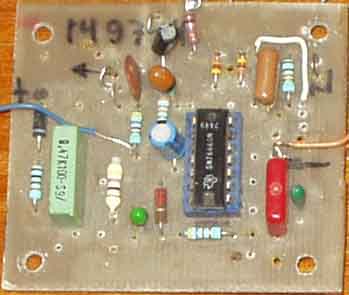
TBA120 as SSB/AM demodulator on print designed by SM4LLP
5b) MC1351P as AM-detector for my Tandberg
Huldra 9 broadcast receiver. IF level input should
not exceed 25mV RMS. The 2nd audio output with built-in audio
amplifier is not used.
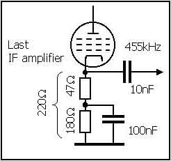
In my Tandberg Huldra 9 the IF stages has a 47W
resistor in series with the cathodes to ground
(without decoupling capacitor), so it is a suitable IF level
across the resistor.
In other cases the existing resistor could be divided into a
smaller and larger value -
as shown here. The IF gain may be slightly reduced on the anode
side of the stage,
but it seems not important, tested it with another receiver.
5c) TBA120 as low frequency mixer.
The circuit is shown as a reference, several other devices
may be better, but it is important to check which input has the
right phase relation to an output to use it
as oscillator. The oscillator uses a Wien-bridge (Vienna Bridge?)
type oscillator with the limiter. If you
wish to use inductors it is no reason for using this oscillator
at all, then the oscillator type using 77 or
88mH inductor may be a suggestion. Some publications are spread
using this device as audio
up-converter for CW Meteorscatter reception, you'll find some
with Google-search for "la8ak"
More similar applications:
MC1496 and S042P as RF- or audio-CW detectors, see page r41
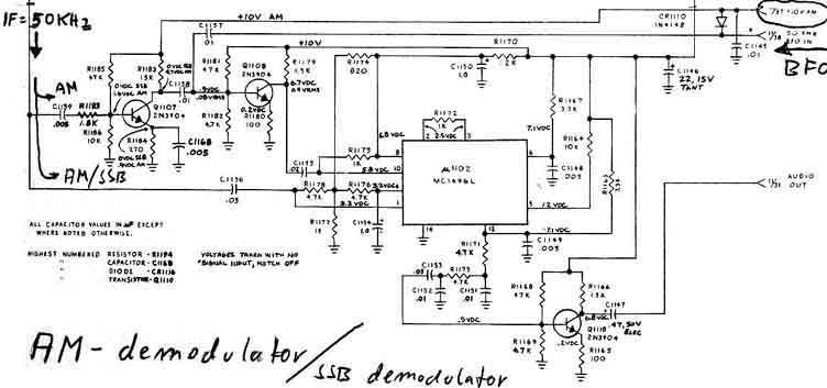
Drake R4245 multi-mode detector (50kHz).
Just came across a circuit diagram for the Drake R4245 receiver
which uses MC1496L as SSB/AM/CW
demodulator on 50kHz - with an extra 2-stage (2N3904) IF limiter
amplifier, and another 2N3904 as audio
amplifier. It would be simpler to use an
FM-IF-amplifier-detector, but I believe MC1496 is better as
detector
as TBA120/SN76660N.
See LF/MF antennas on page L2 (active antenna and frame antennas/magnetic loops)
5d) Siemens TBA120 = TI SN76660N circuit
data, see article by G3TDZ in Radcom
Sept 72 pp 592-595: "Consumer integrated circuits in amateur
design".
 |
 |
Curing
problems with intermittent contact in potmeters
6a) PA Grid Bias
protection. With an extra resistor connected the
voltage
will always swing to safe level (in this
case the bias voltage will increase) if the potmeter
center-contact is intermittent. It is a wellknown problem, I
first experienced it at work with
coast radio transmitters, and later added the modification for
Yaesu FT-902.
6b) Power supply protection against intermittent potmeter.
The voltage will normally
increase when such fault occurs, and expensive equipment may be
damaged.
Here is shown how to avoid it, the output voltage will drop.
Simple Cohn filter for preselector covers 1.75-7.2kHz (LA7MI)
A simple bandpassfilter needs only a single-tuned capacitor.
50W input and output impedance.
It has 30dB attenuation for 2nd harmonic, and 3dB bandwidth on
40m is 80kHz.
LA7MI 2-circuit 80m
pre-selector
This pre-selector has critical coupling. Larger value for L3
gives undercritical coupling and
lower values for over-critical coupling.
Small ready manufactured coils were suitable for L3,
while L1 and L2 are wound on Amidon T50-2. It has ca 50dB attenuation for the mirror
frequency (910kHz aways) when 455kHz IF is used <Amatør Radio Nov.2003 pg. 8>
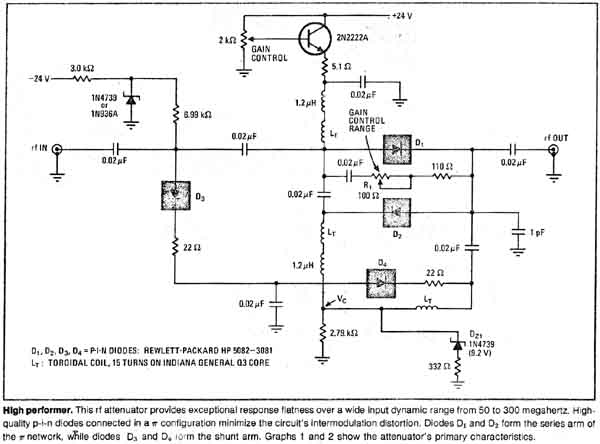
Broadband pin-attenuator has wide input
dynamic range
The circuit diagram was published in Electronics/August 8,
1974 by Roland J. Turner, American Electronics
Labs, Pa
Using the 4th diode should improve the high-level signal
handling. So I used the similar principle for varicap diode
tuned antenna, see page L2
7a) Rig
selector
In my shack it is many different transmitters,
transceivers, receivers which are combined in operation, so a
selector is used for KEY and PTT functions, and connections to
transverters and receivers.
Here is shown the main transmitter selector. It is a problem that
most equipment is powered by 12V or has internal 12V supply, so I
cannot use negative KEY and MUTE voltages. Some transmitters have
higher voltage on the KEY-line. So some converters must be used.
It is not much problem to mount a transistor in a Drake 2-B or
R-4C to convert the signal level such that it uses PTT signal or
other ground-related positive signal for the MUTE. I don't like
relays, and spent over a year removing relays from vital
posititions at Rogaland radio, so it is no reason to have such
rubbish at home.
7b) Here is my old rig
selector and transverter selector
unit
tried to have the receivers through the unit, but crosstalk
between the different RX sides of
transverters was a bad problem, used small screened relays, but
result was bad and I had
to revert to the BNC patch panel for
receivers/antenna/transverters.
I use 14MHz IF for 6m, and 28MHz for 2m, 70cm, 23cm (and 144MHz
for 2320, 5760,
10368 and 24192MHz). HF drive is from FT-7 or FT-902, and VHF
drive is from IC202E.,
separate receivers: Drake 2-B and R-4C.
see transverter control on page d1
Some notes are moved to page d1 (2m), while QRP-notes have been moved to c21
LM3909 LED Flasher.
7e) Had a discussion on sci.electronics.design some years
ago about how long the
LM3909 flashing LED arrangement would last with an AA-cell. 7-8
months later it still
flashes at my entrance, but it may end soon. The type of cell has
proved
not satisfactory for my digital camera, but seems to work for the
LM3909, so it cannot
draw much current - although I use a high intensity LED which has
been taken from
break light panel which was supposed to be used on a car.
 |
 |
 Suggested PCB lay-out |
a) Constant current circuit for feeding high intensity LEDs.
b) Constant current generator for 2 LEDs on a 4,5V lantern
battery.
It seems to be a better idea to try to use a constant current
generator with two outputs. This may work provided the two
silicon transistors are as equal as possible in respect of E-B
forward voltage, and BC557 seems to work fine with better than
10% accuracy. Germanium transistor (AC125) was chosen for the
lower base voltage. For BC557 the important parameter is E-C
saturation voltage and it seems to be 0.1V which is good.
Checking the current against input voltage.
The current rises 10% after warm-up.
| +Vcc | Diode voltage | diode current |
| 3.0 | 2.87 | 6mA |
| 3.17 | 3.01 | 10.4mA |
| 3.45 | 3.1 | 15.6mA |
| 4 | 3.13 | 17mA |
| 4.5 | 3.14 | 18mA*) |
| 5 | 3.15 | 19mA |
| 9 | 3.22 | 23mA |
The measurements were done with R1 =4,7K, but
decreasing the value to 3,3k as shown on the circuit diagram
would only increase the current to 19mA@4.5V supply.
Diode current is measured on the second output, which only
follows the first and as such is sort of worst case.
Only problem is temperature variation of VBE, here shown for
AC162 (AC126) which seems to be the same as for AC125 and AC151
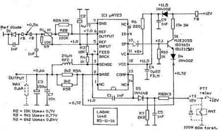
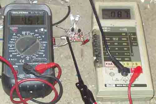
Bias regulator using µA723 or MC1723CP
Improved
circuit for MAR4 application
LA7MI Stein mentions the problem with MAR-4
amplifier, that output impedance
changes are reflected to the input, he suggests this circuit
additon, it has very
good isolation between input and output.
Supply voltage is fed via the NPN-device which also operates as
common-base amplifier and has very good isolation.
Mixer termination amplifiers, see pg. g35
info for winding
coils: http://www.qsl.net/k5bcq/COIL/COIL.html
![]()
Connections for the most common small-signal transistors
 |
 |
 |
2004.09.17
