
c21. QRP experimental techniques
List of related pages:
 a. Antenna
technik
a. Antenna
technik
b. Radio surplus equipment for
amateur radio operation
c. Amateur radio technik
c18. CW handpumps, paddles and
elbugs
c23. QRP transmitter
experiments
c24. Variations in coil
construction
c25. Simple cmos circuits
c61. Components and store
d. VHF/UHF/SHF technik
L. VLF technik
m. Measuing instruments
m11. Grid-dip-meters and xtal testers
n18 VFO topics
n19. Experiments
with ceramic resonators for IF filters
and variable oscillators (QRP pages)
n23. Building
lowcost xtal filters
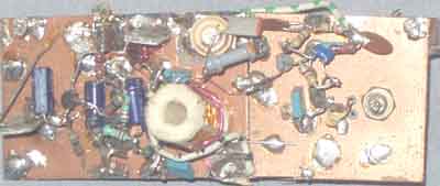
21-1) Low-cost direct conversion receiver for 40, 30, 20m
amateur bands -
uses RA3AAE type
anti-paralell subharmonic mixer with 2x1N4148 diodes
The subharmonic mixer has a great advantage, that no oscillator
signal is radiated through wiring, rectifier and
mains cable and picked up by the antenna, such signal may give a
constant hum modulated signal in the DC-receiver.
Based on the good results (7dB mixer loss) achieved with
bilateral 144/14MHz mixer with 2x 1N4148 using this principle
(see the notes below in 21-7)
it seem interesting to test the concept for a direct conversion
receiver.
It has been so popular engagement in America to suggest hi-tech
solutions for equipment to aid to the
3rd world - without considering that it has never been important
to use expensive components to make a good
construction, in fact the components used here is more what you
will find in a dustbin. It is meant to be an aid
which doesn't mean you have to pass expensive component, when
they already have what you need.
Sensistivity was quite good, a 0.1µV signal could well be heard,
and it was easy to use different value fixed capacitors
with trimmers to covers 20, 30 and 40m bands. The audio filtering
could be better, but the use of an AF-interstage-
transformer between the mixer and the audio with capacitive load
for some sort of tuning to a cw filter may be
a useful way. It was suggested in a Dutch construction, but I
cannot find the article now.
It is very important that the LO-input sees as low as possible
impedance from the buffer, otherwise the mixer will have
considerable high loss. Suppose the coils L3, L4 were 77 or 88mH,
will check it up later, and write some more text
General purpose transistors used in the constructions:
BC547 (TUN) = BC238 = 2N2222 = 2N3904 = MPS3394 etc
BC557 (TUP) = 2N3906 = MPS3702 etc
Some notes on this construction was mentioned in Technical
topics, Radcom April 1995
 |
 |
40/30/20m low-cost receiver direct-conversion using
anti-paralell-diode mixer (RA3AAE).
The RF amplifier coil and transistors are mounted under the
copper-clad board
21-2) RA3AAE bilateral harmonic
mixer with diode pair
In Amateur Radio Topics (G3VA) Sixth edition (pp123-124)
the mixer is mentioned as such: In Radio (December 1976), V.
Polyakov, RA3AAE described a mixer/product detector for use in
direct coversion receivers or VHF receivers. RA3AAE considers
that direct conversion receivers are extremely attractive for
amatuer use but have three main disadvantages; (1)
double-sideband receiver (unless an ssb phasing demodulator is
used), (2) direct envelope demodulation of powerful signals
(oftenparticularly troublesome on the 7MHz band); and (3) local
oscillator radiation unless an RF stageis used. Both (2) and (3)
can be minimized by use of a good balanced or double-balanced
mixer/product detector, but there are many factors that make it
difficult for home constructors to achieve good balance over a
wide frequency range. Several other stages also contribute to
radiation of carrier frequency which is received and causes
interference, often hum-modulated by diodes in the power supply.
 |
 |
RA3AAE's detector is intended to provide an
alternative to a balanced mixer by using diodes providing the
voltage current characteristic shown by the solid line in the
figure b. This is a symmetrical cubical parabola and can be
achieved by two diodes, preferably selected by matching,
connected back-to-back
The operation of the mixer is described by RA3AAE as follows:
"When the local oscillator voltage goes through zero both
diodes are open circuit, and the circuit current vanishes. A the
peaks of both positive and negative halfwaves of this voltage,
one or other of the diodes conducts and the signal source is
connected to the load.
c) In this way the mixer works like a switch closing the circuit
at a frequency equal to twice that of the local oscillator.
Note: L2 must have low impedance on other than the input radio
frequency, L4 must have low impedance on other than the
oscillator frequency. C4 must have low impedance for RF- and
oscillator frequency.
d) RA3AAE points out that the advantage of Fig d over the simpler
scheme of fig c is that it overcomes the loss of signal power in
the coupling to the local oscillator; this drawback is avoided by
using the balanced arrangement using two cubic elements (i.e. 4
diodes)......
How to do it wrong,
here the right side of the diode sees high impedance for the
RF-signal. In spite that the text tells the important facts about
termination impedances, some bad constructions have been sent to
technical topics or built by others who thought it was a proper
construction. When checked, the performance has been louzy and
the reputation has been bad, but too ofter amateurs have no idea
whether a construction is good or bad.
The the two circuits I have constructed use the termination rule
for good performance, and the noise figure was measured for the
VHF version to be increadible low as only 7dB, the same as for
professional made ring-mixers like SBL-1, CM-1, MD108, SRA-1
types.
Further info from G3VA's book "amateur radio techniques! 6th
edition, RSGB, 1978:
Reference:
Check LA7MI's notes about the "Redifon
high-level mixer" on page
n16 to compare RA3AAE type
mixer (Experiments with high-level mixers).
21-3) 3.5MHz "Seiler type" VFO constructed for
operation on 7MHz, for 20m a frequency doubler is needed, and for
10.2MHz reception a 5.1MHz VFO is needed
21-4) Ceramic resonator type VFO covers 3.500-3640kHz with
3.58MHz ceramic resonator.
Since the RA3AAE receiver uses 80m VFO to operate on 40m, this is
an ideal construction, the experiments with
such oscillators were carried out some years after and has not
been used for the receiver since it already had a VFO
which - in spite of using simple components - operated very
satisfactorily.
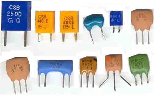
21-5. A variety of the
ceramic resonators for experiments; showing 250, 440, 480, 3580,
960kHz, 5,74MHz,
6.0, 6.0, 3x 10.7MHz
See the notes for experiments with ceramic resonators on page n19
See low cost mixer using 74HC4066
is shown on page L1 (max possible operational
frequency with +10V supply is 7MHz)
Experiments with mixers on page n16
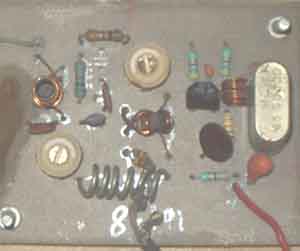
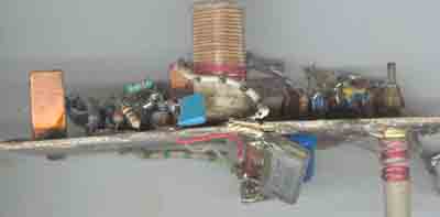
21-6) Ultra Low-cost 14/144MHz RA3AAE-type bilateral mixer.
Construction is not particularly critical. It is important that
the diodes see relatively low impedance on all
associated frequencies. Suppose the optimum impedance seen from
the mixer is somewhere around 60-70W.
The oscillator shown in the photo is not the actual described,
because the original oscillator had spurii at certain
supply voltages and shouldn't be published. This is the first
construction I tried following the principle. Some other
amateurs had already tested this type of mixer, with unsatisfying
results, I suppose the reason was too high
termination impedance for the mixer on some frequencies as some
of the already described circuits used small
coupling capacitors, and I believe this is a wrong application
for optimum mixer diode current.
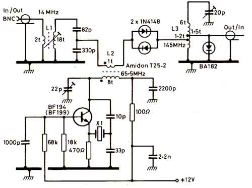
21-7) Bilateral
mixers are, as the name implies , mixers that are
intended to work equally well in converting
a higher frequency signal down to a lower frequency, or withing
changing the configuration, converting the
lower frequency to the higher frequency.
This is a 14/144MHz bi-directional mixer using anti-parallel
diodes in the harmonic mixer configuration
popularized by RA3AAE for hf direct conversion receivers.
Conversion loss approximately 7dB. L1: 5mm dia
core, 18+2turns closewound, 0.3mm enam copper wire. L2 Amidon
T25-2 core, 8+1 turns 0.3mm enam
copper wire. L3 6t, 6mm id - 2cm long18swg tinned copper wire
tapped at 1.2 and 1.5 turns.
The BA182 (BA282) on the output has the only purpose of
protecting the 144MHz port when used with 2m transceivers, but it
is used some more circuitry which is not shown here.
See Technical topics, Radcom August 1985 pp628-629
21-8. Cohn filter
for 1.75-7.2MHz (LA7MI)
Cohn filters are often extremely difficulat to copy, and
some of this kind has been described in
Radcom and QST, but was impossible to work. On the other hand,
here is one which does,
and has been copied with success. A simple
bandpassfilter needs only a single-tuned capacitor.
2nd harmonic attenuation is 30dB, and -3dB bandwidth is 80kHz on
40m. The coils are 90 turns
on Amidon T50-2 iron dust core, and some smaller 2.2µH fixed
coils..
21-9. LA7MI
2-circuit 80m pre-selector
This pre-selector has critical coupling. Larger value for L3
gives undercritical coupling and lower values for over-critical
coupling. Small ready manufactured coils were suitable for L3,
while L1 and L2 are wound on Amidon T50-2. It has ca 50dB
attenuation for the mirror frequency (910kHz away) if 455kHz IF is chosen. It should be a ideal
solution for building simple receivers with 455kHz ceramic
filters.
<Amatør Radio Nov.2003 pg. 8>
21.10 (TR187) 80m 1W QRPP transmitter with
ceramic element and VMOS transistor. A CD3001 is used for
oscillator amplifier and keying. CD4011 and 74HC00 will give
opposite logic key levels.
Another QRP-transmitter using ceramic resonator was shown in
Radcom TT, but uses CD4001 in the oscillator, and in spite of
using a 375pF tuning capacitor the tuning range was small, it is
a better idea to use a TUN as shown here to achieve as large as
possible tuning effect on the ceramic element. With a surplus
20-120pF capacitor the tuning range is 3498-3602kHz, which leaves
some room for spreading, but you wouldn't need the upper cw
segment in any cases. The CMOS buffer gives constant RF level to
the output stage in spite that the oscillator level varies a lot.
Since not all the CMOS device is in use, one could swich
RF-levels between RX and TX.
In the PA is used VK1010 amongst many available. It seems to
operate fb with 1W uncritical output. It has a smaller cooling
fin which is soldered to a larger fin for better cooling.
After the circuit was shown in Radcom G3ILO has tested it and got
0.8W RF o/p with VN10KM. The transmitter covered 3.5-3.6MHz. The
circuit shown in Radcom has some printing faults.
ARRL "Solidstate design shows different solutions for output
matching, but with only 1W output power (ca 50 ohm load on the
transistor) it is difficult to find good solutions. A pi-filter
is not suitable since it requires the output impedance to be much
higher than the antenna impedance, and in this transmitter it
would be waste of ressources.
L1 is 6mm dia coil with iron power core, closewound with 35 turns
0.2mm enam cu wire, ca 6cm long winding. On the lower end is
wound 4turns (2mm wide). With a GDM it is tuned to 3.55MHz. With
the coil I used it seems to give resonnance with 100+100+100pF
capacitors. The circuit has low loaded Q and needs no further
tuning over the band segment.
21.11
Constructional details for the QRPP-transmitter (3.5-3.6MHz).
The transmitter has been described in Radcom TT around 1994 (?),
and in Amatør Radio, TR in Jan 95 pg4. Note the corrected
drawing from it was first published in Radcom.
The circuit is also mentioned on page n18
21.12) Problems and cures for
direct conversion receivers.
Unfortunately simple receivers are too often constructed by
newcomers with little experience, and it takes a lot of
experience to solve all the problems involved in the
constructions. DL0VV 80m dc receiver was described some years
ago, and some Norwegians amateurs tried to copy it, with
different luck. One of those unlucky persons asked LA7MI for
help. He connected the receiver to 12V supply, and what a life,
noise, self-oscillation, but very few stations were heard. The
pacient had to operated soon.
Local oscillator.
The oscillator was checked with oscilloscope. It was pure
sinewave on the oscillatorcoil, but with 10V RF the varicap would
work more like a rectifier than a capacitor. The oscillator
circuit was modified to decrease the amplitude to 3V, but still
the RF voltage was somewhat too high for the varicap diode. The
series capacitor was reduced from 820pF to 68pF. In the antenna
circuit a similar modification was done (820pf reduced to 68pF).
It was now possible to cover the range 3500-3800kHz with the
tuning potmeter.
Audio amplifier.
The audio stages were tested with tone generator and
oscilloscope. It was bad cross-over distortion because the output
transistors were not properly biassed. I was also added a bypass
capacitor to the some transistors, but still the sound was bad. A
22uH RF choke was added to the audio output to attenuate RF going
around and back into the antenna, it helped a lot. A 0.1uF
capacitor was also added across the output to ground and the only
problem unsolved was some bad hum.
RF leak from the local oscillator.
It is a more or less well known problem with RF spread
from the local oscillator, it is more dominant when it is some
mains power supplies in the shack, and in particular when such is
used for the direct conversion receiver. RF is transmitted into
the room and hits the rectifier diodes and modulates with 50Hz,
and signal goes back to the receiver via the antenna. To avoid
this the rectifier diodes should have 0.01uF capacitors across
and the RF detection will not occur.
Wiring style may sometimes be an advantage, but too often the
opposite, it is important to understand about this, some notes
are shown about it on page g32
[First described in Amatörradio nr 6/75, improvements described
by LA7MI in nr 4/82 pp102-103]
 |
 |
21.13) Simple broad-band amplifier using BFR96 (3-30MHz).
21.14) Simple broad band amplifier using 2N3866 or 2N4427
(3-30MHz).
Note that these are not theoretically correct, and the output
impedance may be higher than 50 ohm,
but for many applications it is not so important, so a simple
amplifier is more important to make than
one which has correct output impedance.
I am not so sure about the claimed figures. The
first version has 15dB gain, and maximum safe input level
is -20dBm (25mV). The 2nd has also ca 15dB gain, and maximum
output level (without limiting) is 0dBm
(0.224V). To achieve higher output level a transformer in the
output stage is inevitable, and +16dBm (40mW)
could be achieved. With a transformer the output level is lower
and closer to 50 ohm, see W1FB/W7ZOI's
Solid state design for the radio amateur. More info about such
amplifiers on page L2 and c14.
 |
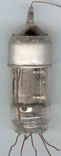 |
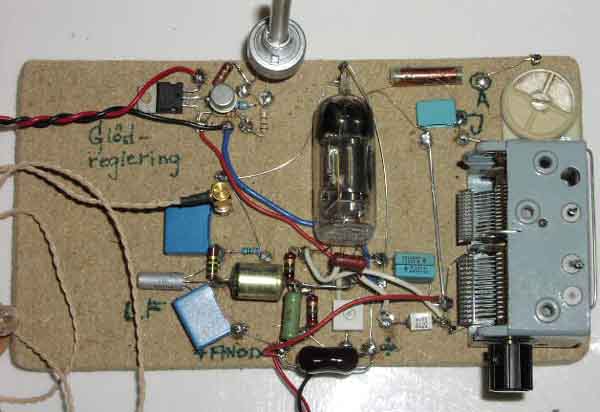
Negadyn RX
Här kommer bild på hur
en första simpel uppkoppling med RV2P800.
Lättarbetad fiberboardskiva med kopparnubb, likadant nu som för 50 år sedan !
Denna typ av mottagare är
troligtvis den ultimata enrörs-mottagaren. Bra
känslighet,mycket selektiv,inga responser via
återkopplingsspole etc.
Tänk om man på något sätt
kunde realisera konceptet med MoS-transistorer med multipla
gatar?
Den gamla OC72àn är för att
få upp LF-en till bra nivå även på svaga stationer.
Istället för den något
bökiga kopplingen med strömreglering till glöden, (LM317+
Hfe-förstärkande transistor + potentiometer) så kunde jag haft
en vanligt trådlindad potentiometer. Dock blir
återkopplingsreglerinen superb på detta vis,mjuk och
lättreglerad. Dessutom så kan ju tillkopplad glödkälla ha
varierande spänning utan att skapa driftproblem.
Carl-Gustaf, SM6HYG
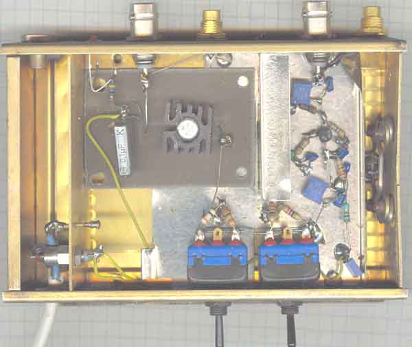
21.15. Distribution amplifiers. The first
amplifier using BFR96 and the 2nd using 2N3866.
Between the amplifiers are connected 10 and 20dB attenuators -
mounted on the DPDT switches.
The BNC and conhex connectors on the input are connected together
for greater flexibility, as are
the two connectors on the output. It might have been an advantage
to put at least one of the
attenuators ahead of the amplifiers to increase the dynamic
range. See the circuit diagram
for the attenuator on page L2. Since the
amplifiers are modified for use on VLF only coaxcables
are not necessary to use for input and output connections, but
the component values shown in the
circuit diagrams above are for HF application.
21.16. LM3909 LED Flasher.
7e) Had a discussion on sci.electronics.design some years
ago about how long the LM3909 flashing LED arrangement would last
with an AA-cell. 7-8 months later it still flashes at my
entrance, but it may end soon. The type of cell has proved not
satisfactory for my digital camera, but seems to work for the
LM3909, so it cannot draw much current - although I use a high
intensity LED which has been taken from break light panel which
was supposed to be used on a car.
 |
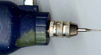 |
21.17. Drill out your own pcb patterns using
normal dentist drills (0.8mm).
LA7MI has made his own pcb patterns this way for 15 years and
have built some miniature 80m transceivers with SMDs.
Norwegian text:
Har laget en tegning for hvordan det gjøres, det er veldig
viktig med en stål-linjal og denne er festet en tynn lærskive
til slik at den fester seg bedre til underlaget, dette er lagt ut
på. Stållinjalen er veldig viktig for at en skal klare å styre
boret (0,8mm dia), ellers blir resultatet veldig hullete og en
klarer ikke holde boret stødig. Bruker en liten 12V batteridrill
fra Völkner (Model AD9, 9-18VDC, 8000-18000 rpm).
info for winding
coils: http://www.qsl.net/k5bcq/COIL/COIL.html
a variety of coils /la8ak/c24.htm
 BC547 BC557 |
 2N4401 MPS3394 |
 |
 VN2222 |
 |
 |
 |
 |
 |
21.17. Connections for the
most common small-signal transistors
 BD135, BD139, BD136, BD140 MJE340. MJE350, MJE2955, MJE3055 |
 TIP122, TIP127, BDX33. Note that these are connected the opposite way around compared to the devices to the left side |
Some more commonly used devices
Minimum loss pad, an easy, but correct match - connection between
50 and 75 ohm systems
Last update 2005.03.17
