
n18 Oscillator topics (free-running)
Oscillators with ceramic resonators, see page n19
Xtal oscillators, see page n20

n18
Oscillator topics (free-running)
Oscillators
with ceramic resonators, see page n19
Xtal oscillators, see page n20
Note: On this page is shown oscillators which are also found on the other pages on this site.
Audio oscillator
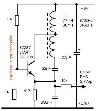
Audio oscillator using 88 or 77mH toroid coil (pupin
coil for telephone line). Just a reference circuit, but one may
sometimes need such; perhaps for another frequency. It was made,
based on experience with 50kHz BFO for Drake 2-B, and later
alternative BFO for R-4 - CW-meteorscatter product detector as
plug-in unit on the rear of the receiver.
(The oscillator is also shown on pg c11).
Audio oscillator
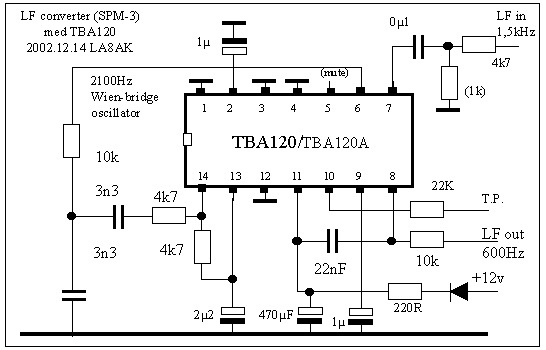
2100Hz oscillator with TBA120 as low
frequency mixer. The circuit is
shown as a reference, several other devices may be better, but it
is important to check which input has the right phase relation to
an output to use it as oscillator. The oscillator uses a
Wien-bridge (Vienna Bridge?) type oscillator with the limiter. If
you wish to use inductors it is no reason for using this
oscillator at all, then the oscillator type using 77 or 88mH
inductor may be a suggestion. Some publications are spread using
this device as audio up-converter for CW Meteorscatter reception,
you'll find some with Google-search for "la8ak".(The
oscillator is also shown on pg c11).
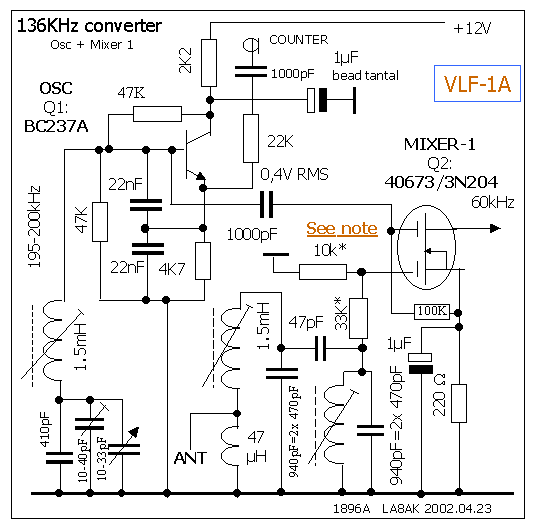
195-200kHz Clapp-oscillator for MOSFET mixer.
The power gain for this simple dual-gate mosfet mixer is rather
high. It was soon learnt that in spite
that I didn't hear MSF when listening to 60kHz
(with the active aerial), it did break through the IF, and 40dB
IF rejection was neccessary with active aerial on 136kHz at this
QTH in (Kristiansand, Loc: JO38XC, South Norway),
therefore it is shown a two stage input filter.
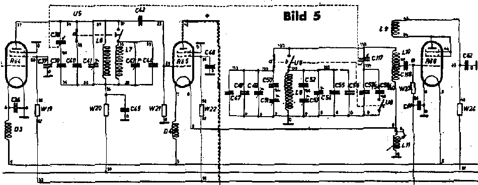
German transceiver 15W.S.E.a RX mixer and Local
Oscillator
Note the cathode injection on detector (using battery-type valve
RV2,4P700) to the left side of the circuit diagram, a comparable
circuit is found in WS38 where the local osc has signal tapped
from the filament side. See more details on page 31a
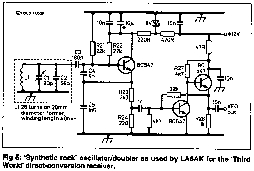
Seiler type VFO, constructed for the
receiver (the doubler is not shown on this circuit diagram). I
was later told that the ratio between C4 and C5 is wrong, it
works, but would be better with equal values - say 2x 2200pF
styroflex or film type. If varying output voltage is not a
problem (when driving CMOS devices), the clapp type oscillator is
usually easier to construct.
It is also shown on page c21
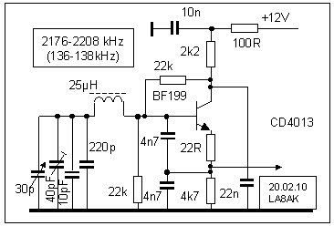
2176-2208kHz Clapp-type variable oscillator . It was intended to
be used with a divide-by-16 divider to cover 136-138kHz band, so
it is no problem concerned with using a clapp oscillator with
varying output level
Also shown on pg
L90.
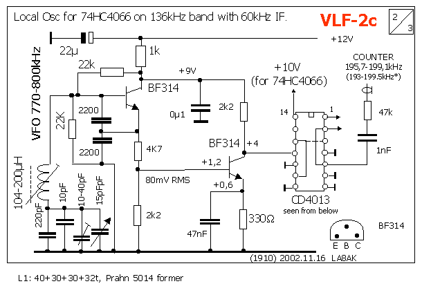
770-800kHz clapp-oscillator, as local osc.
for 74HC4066-type converter . The oscillator has an output
of 195-199kHz. It is easier to build a VFO on a higher frequency
and divide to to 195-199kHz, since it requires more readily
available coils. Little further is to be said, but I was
surprised that only one stage was needed to achieve good
limiting.
BF314 were chosen since it is available free in large quantities,
but I suppose any 2N2222, 2N3904, BC237, BF199, BF224 and many
other types would do the job just fine.
This circuit is also shown on page L1
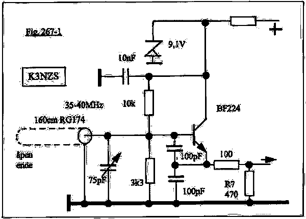
Variable oscillator using RG174 coax cable which has been
described in QST (10/1980)
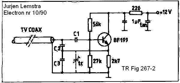
Jurjen Lemstra's VFO, see Electron nr 10/90
| cable length | C2 (pF) | C3 (pF) | C1 (pF) | Frequency |
| 7,5cm | 100 | 50+40 (tr) | 5.6 | 88-100MHz |
| 35cm | 250 | 250 | 80 | 28.420 |
| 50 | 250 | 160 | 33 | 26,362 |
| 136 | 100 | 33+40tr | 6.8 | 25MHz |
| 136 | 1000 | 1000 | 82 | 9.150 |
| 136 | 2000 | 2000 | 82 | 6.580 |
| 136 | 3200 | 3200 | 80 | 5.151 |
| 136cm | 10nF | 10nF | 1200 | 3.188 |
| 5.00m | 10nF | 10nF | 1200 | 1.892 |
Component variations for Jurjen Lemstra's VFO
(AR nr 5/97 TR 267 pp138)
Will provide some text later
3W power oscillator for 80m using EL84/6BQ5, see page n12