
n19 Experiments with ceramic resonators
Simple QRP transmitters
Free-running oscillators, see page n18
n19 Experiments with ceramic resonators
Simple QRP transmitters
Free-running oscillators, see
page n18
Please note: It seems impossible to bring all the text within the near future, so references are made where the circuit diagrams are found, but I hope to put some text later, most source is G3VA's technical topics, Radcom, and some need to be written or translated from Norwegian or other notes. It takes a lot of time to scan and prepare the drawings for best possible presentation. It is overlooked for other site owners, but I hope to improve on this later, some drawings may need to be redrawn, see note below.
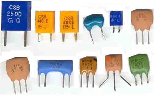
A variety of the ceramic resonators and filters for experiments;
showing elements for 250, 440, 480, 3580, 960kHz, 5,74MHz,
6.0, 6.0, 3x 10.7MHz
The reason for using BJT instead of FET or CMOS is that
capacitance variation is larger and still achieve oscillation,
others prefer simple circuits with
considerable smaller tuning range. I find a general purpose
transistor (2N3904, 2N2222, MPS706, MPS3394) to be no real extra
problem to include.
Variable frequency ceramic oscillator covering 3500-3640kHz using
a single 3.58MHz ceramic resonator element
Radcom TT May 94 pg55
80m 1W QRPP transmitter with ceramic element and VMOS transistor.
A CD4001 is used for oscillator amplifier and keying. CD4011 and
74HC00 will give opposite logic key levels. With an extra BC547/BC238/2N3904
(TUN) it is possible to achieve considerable larger tuning range
than with the CMOS device alone.
Constructional details for the QRPP-transmitter (3.5-3.6MHz).
The transmitter has been described in Radcom TT around 1994 (?),
and in Amatør Radio, TR in Jan 95 pg4. Note the corrected
drawing from it was first published in Radcom.
See page c21
for more constructional details
Radcom TT (G3VA), Feb 1996. 3.5MHz ceramic-resonator VXO for 7MHz
direct conversion transceiver
The zener diode is drawn in wrong direction.
Radcom TT June 99
IF filters using ceramic filters
 |
 |
G3JIR Ladder filter using ceramic resonators. Radcom TT June 99
pp60-61
Refr.: G3UUR's Crystal & Ceramic filter miscellany, Radcom
TT, Nov 99 pp60-61
 |
 |
Ceramic filter for 12.5kHz spacing, G3JIR Radcom TT March 2000
pp64-65
Radcom TT July 2002 pg61: Using ceramic IF filters in VFOs
(Constructor: LA8OJ)
Ceramtic filter as 455kHz BFO, G8SEQ
Radcom TT, Oct 2002, pg 64
 |
 |
Further experimental VCXO's using butler type oscillator (2002.05.16)
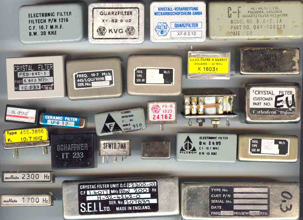
A variety of xtal- and ceramic filters.
Procedure to provide best images
for black/white drawings:
Many presentations found on internet sites are bad, and indicate
that the provider offers too little time for editing the files,
or perhaps he knows nothing about it. Drawings are now scanned
using IrfanView3.91 and HP scanjet 3500c, saved as jpg, then
opened in Adobe Photoshop, contrast incresased as far as
possible, redundant space removed, and image size decided. Then
back to Irrfanview and colour depth decreased to B/W and saved to
gif. It makes a small file size as possible, possibly only 1/5 to
1/10 of comparable jpg file and much sharper. Earlier I had to
keep Win95 because the driver with an old scanner was the only
possibility to provide gif files, now things are changed with
IrfanView 3.91.
![]()
Last update: 2005.03.14