
c14 - Low Power Amplifiers
tech notes under editing (amplifiers)
see also notes under VHF and Nöding.com
Noise source and bandwidth measuring equipment,
see page c13
QRP power amplifiers, see page c23
2)
Alternative high-input impedance amplifier (L2)
Alternative high-impedance amplifier
for uncritical applications (suggested by LA7MI
in
1973). May well be used for a tuned frame aerial, but not for a
broadband type active aerial.
It has gain, but you should be careful to adjust it too high, and
the positive feedback to the
gate circuit should be used with care, or avoided if possible.
I used it for active antenna and tuned frame aerial covering
500-4000kHz in 1973-1985,
also used in many measuring instruments.It is normally flat up to
above 10-15MHz,
the lower limit depends on the capacitor valuess. See also page M2
3) high
input impedance amplifier using valves (L2)
Suggested high impedance amplifier as
active aerial using thermionic valve - a circuit meant
for our boatanchor friends. The suggestion is based on experience
with J310, a pentode may
be easier to use than triodes, suggest E83F, E180F, E280F.
It is important to use the large
toroid core such that you can use pvc-coated wire for sufficient
insulation, the Amidon cores
are too small. Spurious killer resistors in anode and grid seem
important to remember.
It seems to be some interest for this construction, and it is
copied to another site.
One advantage is that input overvoltage protection is not really
necessary - at least not for
anything but direct lightening stroke. It was suggested for the
boatanchor fraternity, but it
seems to be some other parts, too.
30dB gain broadband amplifiers
without transformers. (L2)
Broadband amplifiers with BFR96 and 2N3866
It seems that amplifiers without output matching transformer has
5-6dB lower gain per stage, and
max output level has 10-15dB lower limit.
13b) Amplifier for
VLF signal generator (pg L2)
If you don't have a generator capable of 1V RF level, here is
shown a 20dB gain amplifier, maximum output
level is 40mW (+16dBm or 2V RMS in 50W). The limiting factor is collector voltage swing
which is then 5.6Vpp.
It uses off-the-shelf components. Current drain is 120mA, but
depends on the E-B voltage of the PNP transistor
and resistor R4. The transformer has 250µH per coil and it is
useful for a broadband-amplifier. Other suggested
transistors types are Q1=BD135, BD137, BD139, Q2= 2N3906, BC557,
BC558. Bandwidth within -2dB drop of
gain is 80-3500kHz, so if you need something to cover larger
range you must use a UHF-transistor like 2N3866,
2N4427, BFR96 or other. To increase the gain on lower
frequencies, a higher inductance transformer and larger
capcitances are necessary. 0.1µF was chosen simply because it
was free, it is almost too small for 136kHz.
With only an RF choke the gain will decrease a few dB, but the
maximum RF level will inctrease by the same
amount. It is explained in Solid state design for the radio
amateur (pp189 fig 18) that output impedance increases
and as such you loose gain.
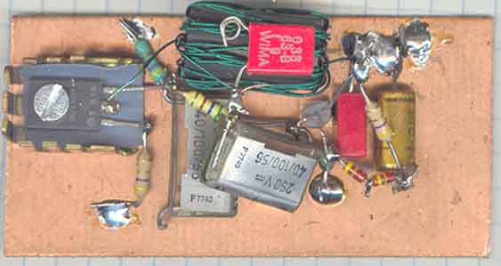
The amplifier is mounted on
35x75mm pcb laminate. Cooling fin is
needed and it gets quite hot.
The red capacitor over the transformer is output connection. I
haven't the faintest idea what or where
the ferrite cores comes from, but there were hundreds of them,
and they are free, possibly easy to find
a better type for those who like to pay.
Calculating coil, capacitors,
inductance (pg L2):
Below 1MHz, use nF, kHz, mH
info for winding coils: http://www.qsl.net/k5bcq/COIL/COIL.html
pg-994.
Index for technical topics
 e/m
e/m
2004.12.27