
Jan Martin Nöding
Info
for E10K, E10L (FuG X Bordfunkgerät)
Links to other pages on this site:
e11.
Receiver's Intermediate Frequency List
e12.
Data for German communication receivers
23e. EZ6
(FuG VI)
24a.
Receiver circuit diagrams and notes for E52b
24b. Mw.E.c
30e.
FuG X 'matching' transmitters
30g 10WSc,
EBL3, Feld.Fu.b,
Technical articles under preparation
(received from PA0SE Dick Rollema):
10a Introduction to German World War
II Radio Equipment
12a. German World War II Radio Equipment - Köln
E52 receiver - part 1 (PA0SE Dick Rolema)
12b. German World War II Radio Equipment - Köln
E52 receiver - part 2 (PA0SE Dick Rolema)
12c. Lorenz Shortwave Receiver Lo6K39a
(Lo6L39), The ultimate TRF set [PA0SE]
12d. Telefunken World War II Superheterodyne Receiver Kw.E.a
(Lw.E.a) [PA0SE]
12e. Telefunken World War II Universal TRF receiver Torn.E.b
[PA0SE]
 |
 |
E10K and EZ6
 |
 |
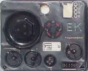
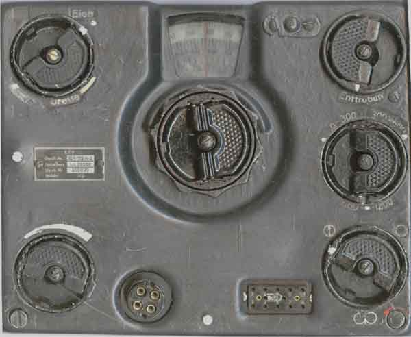
E10K (E10L) versus EZ6
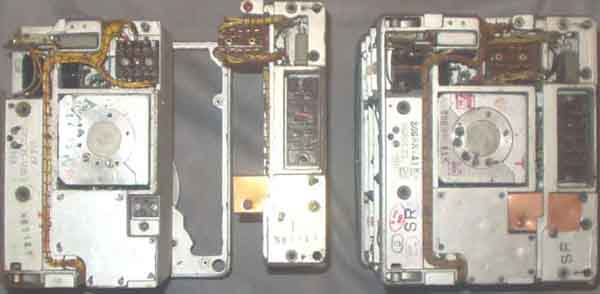 two different E10K's seen from the rear side; two parts unplugged |
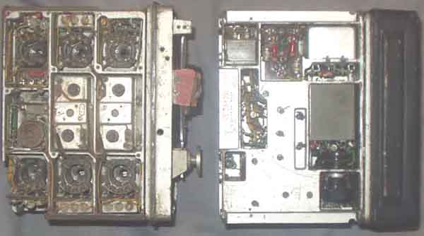 seen from above and below |
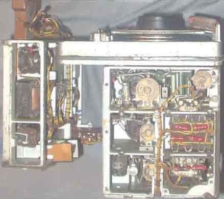 seen from the "left" side |
|
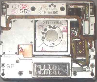 rear |
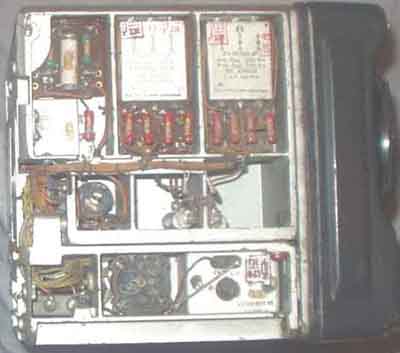 right side |
E10K seen from different angles, the receivers are easily divided into smaller units (Baugruppen)
Mounting frames for the FuG 10 equipment are shown on page 30e
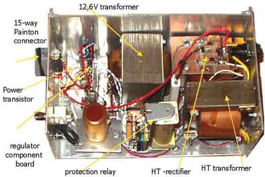
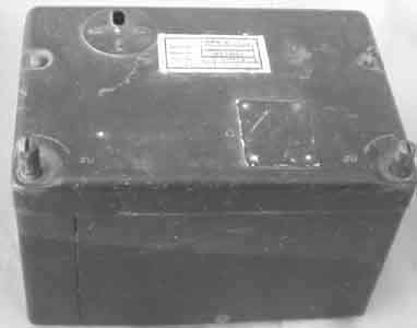
Power supply for Luftwaffe receivers
Power supply for
EZ6, EK10, EL10 and other receivers
EZ6, EL10, and EK10 require 25.2VDC and
+210VDC. Perhaps not too critical. They will work with 12.6V
heater -
without any hum problems, but the motor in EZ6 will of course not
operate.
EZ6 motor supply isn't solved with 25VAC, and I haven't
investigated into running it, it might operate with a simple
rectifier to +24V, but it is only a cosmetic problem - as long as
you don't have any of the DF antenna
system to go with it, you have no need for installing the motor.
It isn't really neccessary to use stabilized anode supply, but
the problem is to find suitable mains transformers,
so I decided to use a regulator.
Have already built supplies with EL86 type shunt regulators, but
with the available components it seems
better idea to use a series regulator. LA4OE runs his EZ-6 with
150V supply voltage and it still works fine.
With +200V supply EZ6 draws 38-40mA anode current, 2mA more with
BFO, but less for strong signals.
Considered some different regulators. A valve is better if the
voltage drop over the regulator is large, but
today you can always find some mosfets to use. Problem with high
voltage BJT's is that they have very low
current gain, and only few have in the region of HFE=10, so you
need to make a darlington circuit.
I will eventually build such regulator later, but this was made 8
years ago dependent on available components.
Philips EL86 has proved to be a very useful valve since it will
draw 100mA triode connected with only 100V,
it is difficult to find another valve to do the same, with
similar size and heater current.
Other valves requires higher screen voltage, but this is always a
problem when limited supply voltages are available..
In my construction the voltage from the rectifier varies between
250-290V,
it means that the regulator have
minimum 40V across it, and maximum 80v. So unless you don't
shortcuit the output it is no real danger
with a 100V device, you may also use a zener diode across it to
protect it. I used a Radio Spare
device which stands at least 200V, but I have no data.
Another problem with shortcircuit is that the small transistors
Q3, 4, 5 are very likely to
have secondary breakdown. Even the old 2N398 will work
satisfactorily, but it burnt out when I tested
the supply, only because of my stupidity. The 1k resistor in
series protects agains such, and you many very
well use cascade of lower voltage devices instead of searching
for a 300V type. I have lots of such, but find
it interesting to prove that low cost devices will work just as
good provided you take proper steps.
It is very important for valves to have soft start in heater
supply, it may increase the life-time a lot, so
I still hope to have the over 60 years old valves for many years.
The relay was measured and operated
with the current shown. You just look for a higher voltage relay
and make some tests to find the optimum relay
(which draw as little current as possible, often AC relays will
give best results in such respect).
In order to avoid damages if output is shortcircuited a smaller
value resistor is inserted in series with the fuse,
it will slow down the transient so the fuse have time to blow
before the power supply.
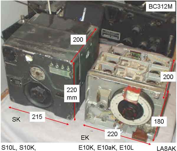
FuG10 measures
Amplifier V350a
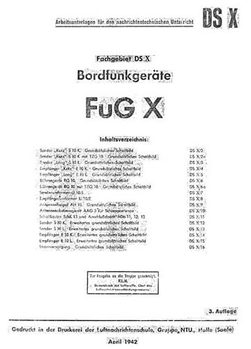
Fachgebiet DS X: Bordfunkgeräte FuG X
(FuG10)
Arbeitsunterlagen für den nachrichtentechnischen Unterricht
Aktuell artikkel i Amatör
Radio:
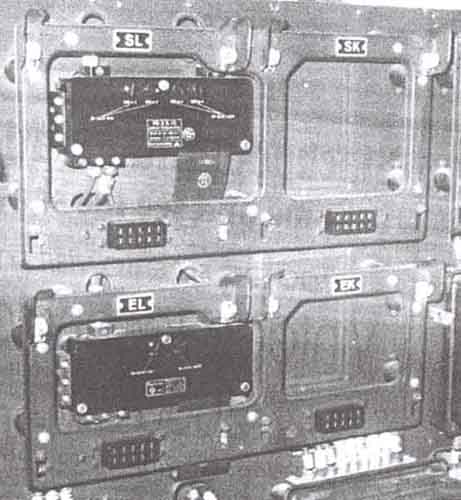
EK10, EL10, SK10, SL10 kontaktlistene...... AR 50-06-146
2005.02.22