
e12. Short data for German Radio-Communication Receivers
e12. Short data for German
Radio-Communication Receivers
 e11 Receiver IF and short data List I (German)
e13 Receiver IF and shortform data list II (non-German)
e71
Some books about German equipment to consider
 f11 Further receiver data
e67 Radio equioment and
accessories (Funkgeräte und Zubehör)
g37 IF standards
e86 German valves and later reinventions in MOCKBA, CCCP
e87 Dumpbuizen voor VHF en
UHF (not ready)
11c List of some surplus
equipment
e. German communication
equipment
Page 994 shows list of contents for this site
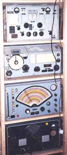 |
 Unfortunately not mine! |
 |
 |
 |
Regenerative Receiver type
abbreviations:
0V1 = Detector and audio stage,
1V1 = RF, Det, Audio,
3V1 = 3x RF stages, detector and audio stage,
1V2 = RF, detector and 2x audio stages.
15W.S.E.a and 15W.SE.b (see page 31a)
AQ2/3 and AQ2/4 receivers,
see more info on page 23g
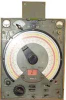
CR101 (Philips).
It can definitely not be
compared with CR100, the latter seems somewhat more advanced than
CR101
circuit
EF8 1.RF amplifier
EF9 1.RF amplifier
ECH3 Mixer and L.O.
EBF2 1st. IF
EBF2 2nd IF and AGC detector
EBF2 Detector and audio
EBF2 BFO
EM4 Indicator
Selenium bridge for noise limiter
Type 1918 heater regulator
Type 13202X Neon for RF input protection
150C1 150V stabilizer
8091D00 Dial lamps
AZ1 two-way rectifier
Xtal filter (IF=750kHz)
Ranges:
1) 30-18MHz, 2) 18-11MHz,, 3) 11-6,6MHz, 4) 6,6-4MHz, 5)
4,0-2,4MHz, 6) 2,4-1,5MHz
Audio output impedance: 2500 ohm
Image rejection: Band 1) >40dB, 2) >64dB, 3)
>76dB, 4) >90dB, 5) >92dB, 6) >92dB.
Weight: 28kg
Measures: Width= 483 * Height 310 * Debth= 370mm
Mains operated.
E10K
E10K 3.0-6.0 MHz ZF: 1600kHz (1460kHz?)
8* RV12P2000
The receiver has fixed BFO frequency (E10L has variable pitch)
See
more specific info and measurement for the receiver on page 23a
|
 |
E10L vs. EZ6
E10L
300-600kHz ZF: 160kHz 8*RV12P2000
The receiver has variable BFO
(although some circuit diagrams show E10K instead)
See
more specific info and measurement for the receiver on page 23a
E24 Receiver
(Bordfunkgerät FuG24, Werkschrift 4013, januar 1945)
E52a, E52b
'Köln' = T8K44
Frequency ranges:
1,6-2,9 3,2-5,8 6,5-9,7 10,6-17,0 18,6-24,2MHz
10x RV12P2000, 2x RG12D60, STV140/60, Urfa 610, 2x OB120/4 (dial
lamps).
Circuit: RF, RF, MIX, LO, IF, IF, IF, Det/Audio, Audio
output, BFO
IF= 1MHz, 2x xtal filter and 6. order IF LC-filter,
bandwidth 0.2-5kHz continously variable
See
more specific info and measurement for the receiver on page 24a
E381S (Telefunken), original version is
E381H.
Frequency ranges: 14.6-45.5, 41.7-136.4, 122.9-411, 366-1250,
1160-4290kHz, 3.48-6.1,
4.8-8.35, 6.6-11, 8.95-16, 14-20MHz
Valves: RES094 (RF), 3x RE084 (Detector, audio and audio
output stages)
Audio output impedance: 4000 ohm.
Sensitivity: 0.5-50µV 1V audio voltage into 4000 ohm for A1. For
A3 (30% modulation): 1.5-90µV.
Supply voltages: +4V 0,35A, +100V 20mA, -1.5V, -3V.
Marine version has emergency crystal detector, while airforce
type has an extra notch filter
See
more specific info and measurement for the receiver on page 17s
Compare with Philips H2L/7
E538F 1/39,
Funk-Peil-Anlage - Fu.Peil A 60, D.(Luft) T.4702 (W. Gierlach)
ER1a [SEI] Allwellenempfänger (Ln25472)
ZF=468kHz
I (grün) 22000-7500, II
(rot) 7500-2500, III (gelb) 2500-850, IV (blau) 850-290, V
(weiß) 290-100kHz, VI Tonabnahmeranschl.
See
more specific info Radione receivers on page 25r
EZ2 A, s. D.
(Luft) T.4066 Fernbediengeräte FBG5, EFB2, (W. Gierlach)
.............. D. (Luft) T.4061 Automatischer Peilzusatz APZ5, (W. Gierlach)
EZ6 (FuG10 P) Zielflug Empfänger
(Homing receiver)
Frequency ranges: 150-300, 300-600, 600-1200kHz
IF: 130kHz , xtal filter. Bandwidth 400-2.4kHz (later
version has not variable selectivity?).
Valves: 9x RV12P2000 + STV100/25(?)
Power requirement: 28V 0.6A. Dynamotor: U11, U11a
The direction indication principle and simplifed circuit is shown
in "Die deutschen Funkpeil-
und Horch-verfahren bis 1945" (F.Trenkle) pp146 (FuG16).
See
more specific info and measurements for the receiver on page 23e
|
 |
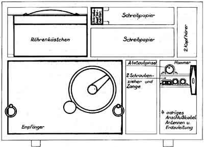
EZ6 vs. Mw.E.c
BC453 - another rig - often used as Q5'er, see more info on
pg-f11
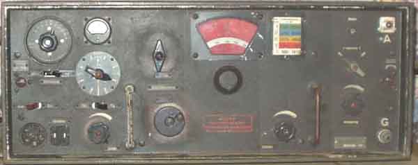
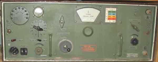
EO8268 Schwabenland (Marine version), see Ln 21021 below (is it E08268 or EO8268?)
FE52 (Blaupunkt)
19 valves.
Weight 35kg, 690mm long x 445 high x 470 deep
1. 1,6-2,1MHz, 2. 2,1-2,7MHz, 3. 2,7-3,5MHz, 4. 3,5-4,5MHz, 5.
4,5-5,3MHz, 6. 5,3-7,6MHz, 7. 7,6-10MHz,
8. 10,0-13,2MHz, 9. 13,2-17,3MHz, 10. 17,3-22,6MHz, 11.
22,6-30,0MHz
Sensitivity ca 10kTo
Image rejection 1,6...17MHz: 95dB, 17...23MHz: 80dB, 23...30MHz:
70dB
IF rejection: Better than 95dB
IF: 1450kHz(?) and 300kHz(?)
FuG25a,
See
more specific info and measurements for the receiver on page 29a
 |
 |
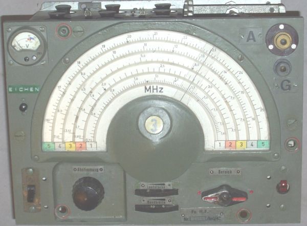
Fu.H.E.c Funkhorchempfänger-c
(DF/Monitoring receiver)
Circuit: 10x RV2P800 as
RF, RF, MIX, OSC, IF, IF, IF, Audion detector, Audio output,
BFO/CAL. 2x Sirutor 5b as AGC rectifier.
IF= 1875kHz, single xtal-filter. Xtal controlled BFO:
1874.1/1875.9kHz.
Frequency ranges: 1. (White) 3.53-5.94MHz, 2. (Red)
5.77-9.68, 3. (Yel) 9.40-15.80, 4. (Blu) 15.35-25.80MHz.
Power requirement: 2V 1.9A, 90V 20mA. Automatic bias from anode
current.
Converter for 12V operation EW.h.
Measures: 430H x 340W x 240D, Weight: 27kg
See
more specific info and measurements for the receiver on page 22h
 |
 |
Fu.H.E.u (Funkhorchempfänger
'u' = Monitoring receiver)
Frequency ranges:
0.73-1.65, 1.65-3.5, 3.5-7.5, 7.5-16, 16-25MHz
IF= 470kHz. Calibrator xtal: 2000kHz
Circuit: 9x RV2P800 as RF, MIX, Local osc, IF1, IF2,
Audion detector, Audio, Calibrator, BFO.
Power: 2V 1.8A, 90V 20mA. Automatic bias from anode
current.
Measures: 453H x 365W x 250D. Weight 22kg(?)
See
more specific info and measurements for the receiver on page 22h
Fu.H.E.v (Funkhorchempfänger 'v' = (Monitoring receiver) (1942)
Frequency ranges 25-38, 35-56,
53-95, 85-176MHz 8x RV2.4P700 + SD1A, ZF:
3.25MHz
see picture at http://www.laud.no/la6nca/staaland/index.htm
 |
 |
H2L/7 (Philips) Allwellen Empfänger, 1V2 type receiver
Frequency ranges:
15-46, 46-135, 135-400, 400-1050,
1050-2750, 2750-7500, 7500-9600, 9600-12500, 12500-15700,
15700-21000kHz
HF B442 (H410D), Audion B424
(RE084K), NF B424 (RE084K), Endstufe B443
(2364D: Manual printed at Druckerei "Krakowska",
Litzmannstrasse 10, Warschau)
- compare with type E381
See
more specific info and measurements for the receiver on page 23p
HE.1 (Fl 26 587) [Telefunken]
Lang-Mittelwellen-Horch-Empfänger (Juli 1937)
Frequenzbereich: 75-3333kHz (Betriebsart: A1/A2/A3).
Zwischenfrequenz 56kHz
RES094 Hochfrequenzröhre, RE084k Überlagererröhre, RES094
Mischröhre, RES094 Zwischenfrequenzröhre,
RE084k Audionröhre, RE084k Niederfrequenz-Verstärkerröhre
Batteriespannungen: Heizspannung 4V, Schirmgitterspannung
45...55V, Anodenspannung 90...100V
Maße und Gewichte: Höhe etwa 505mm, Breite 365mm, Tiefe 230mm,
Gewichte etwa 20kg.
Ha5K39b (Hagenuk) Receiver type 1V1, 2-5MHz, 3x RV12P2000.
The transmitter has 2x RV12P2000 and RL12P10
See
more specific info and measurements for the receiver on page 31h
A slightly modified receiver

HMZL34
OKM [Philips] (see
VO34) 4x EH2, 4x EBC3, EL2, Typ1461, 4687, 13202X, ZF=280kHz
VO34 [Philips] (Vliegtuig Ontvanger 34).5x
EH2, 3x EBC3, EL2, Typ1461, 4687, 13202X, ZF=280kHz
Original receiver is VO34, a Dutch aircraft receiver which
Germans used under designation HMZL34.
Systemized to use only 3 types of valves, but unlike the Germans
they chose a heptode instead of a pentode.
It is few differences: BFO valve EH2 was changed to EBC3 (to
avoid using an extra signal diode), and
some changes in the heater circuit (and heater voltage?).
Rather unique waggon where the RF-coils are mounted, perhaps
Philips'
version of HRO. Must be seen!
Mains operated.
See
more specific info and measurements for the receiver on page 23q
Jo20K42 (RX data only) - Wilhelm Johnsen A/S
Kopenhagen, Denmark.
Range: 15kHz-24MHz.
IF= 460kHz??
Circuit
EF8 1.RF
ECH3 MIX/Osz
EBF2 IF + detector
EBF2 detector and audio
EL2 Audio output
EF9 BFO
EM4 signal indicator
Audio output impedance 4000 ohms
Power requirement: 12V DC, 275V DC.
K126X
(Frequenzmesser) 30-214,
214-2000, 2000-15000, 15000-30000kHz
RES094 (HF-Stufe), RE134W (Audiob), RE134 1. NF-Stufe), , RE134
2. NF-Stufe)
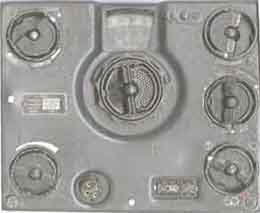
KST (Körting)
copy of
National HRO using German steel valves
IF=468kHz, xtal
filter.
Ranges:
1. 45-22MHz (special range)
2. 22-11MHz (normal)
3. 12-6MHz (normal )
4. 6-3MHz (normal)
5. 3-1.3MHz (special)
6. 1100-300kHz (special)
7. 400-185kHz (special)
Circuit: 1.RF EF13, 2.RF EF13, Mixer EF13, LO EF14, 1.IF
EF11, 2.IF EF11, Det/Audio EBF11,
Audio output EL11, BFO EF14, Rectifier AZ1.
Power requirement: 220V 70W.
See later model of National HRO on page 62
See SSB notes on page f12
K.w.E.a - Kurzwellenempfänger
"Anton"
I 980-1610kHz (Wht)
II 1560-2550 (Red)
III 2470-4060 (Yel)
IV 3940-6395 (blu)
V 6205-10200 (grn)
Circuit: 11x RV2P800 as 2 RF amplifiers, mixer, 3
IF-amplifier, AGC IF amplifier
and dry-diode AGC rectifier (2x Sirutor 5b), BFO/Calibrator
(250/250,9kHz
xtals), Audion detector, Audio amplifier. 2x TE30 RF protection.
One or two tuned circuits (selected by a switch) ahead of first
RF amplifier, two tuned circuits
between first and second RF amplifier, and one between 2nd RF and
mixer
plus one section for local oscillator. 3 double-tuned IF
amplifier LC-circuits for variable selectivity.
Reduced IF level to detector for CW (with BFO). Audio filter for
selectivity position 5-7(8).
Position 7 and 8 have equal selectity, but BFO frequency is 251,8kHz
for position 8.
Meter for anode currents and supply voltage.
Antenna: 200...500pF capacitance
Sensitivity for 1V RMS output into 4000 ohm, single input
circuit, without AGC:
Telephony, range I-V: 3...5µV
Telegraphy range I-IV: 0,5-2µV, range V: 1...2µV
IF= 250.9kHz. BFO=250/251.8kHz
Selectivity:
bandwidth position offset signal signal attenuation
1) Telephony 4-12kHz 40dB (100:1)
2) Telephony 3-10kHz 40dB (100:1)
3) Telephony 3-9kHz 55dB (500:1)
4) Telephony 1,5-5kHz 55dB (500:1)
7) Telegraphy 1,8kHz 55dB (500:1)
Image rejection: At least 78dB (8000:1) @10MHz.
RF and AF
gain controls are normally combined when AGC is on, but possible
to
choose separate gain controls as without AGC with internal
selector (switch).
RF gain is achieved by varying the gain on certain RF/IF valves
with variable
screen grid voltage, but it is not the same valves as have AGC
applied.
Audio output impedance: 4000 ohm.
Power supply: 2V accumulator and 90V anode battery
(automatic bias from anode current).or
Netzanschlussgerät NA6/NA6a.
Converter for 12V operation EW.d and WS(E)d.
Measures: Height 274mm, width 692mm, depth 346mm
Weight 42kg
Acessories: 2 headphones Dfh.a, 5 core cable w/connectors
for supply voltages,
DF-unit (FuPeil A70a). FuPeil A70 d, e, f, h for
KwEa.apt), see "Die deutschen Funkpeil-
und Horch-verfahren bis 1945" (F.Trenkle) pp145.
My favourite receiver. Unusual extra IF stage and voltage doubler
for AGC, and level matched IF
level for CW (SSB). AGC performs very well for SSB reception
(provided BFO injection is increased).
Problem today: Backslash is a problem, particularly on the 40m
band.
See
more specific info and measurement for the receiver on page 22b
SSB notes on
page f12
L.w.E.a. - Langwellenempfänger 'Anton'
 |
|
Lw.E.a
vs. Kw.E.a
I 72-128kHz (wht)
II 122-241kHz (Red)
III 230-430kHz (Yel)
IV 410-800kHz (Blu)
V 760-1525kHz (Grn)
Circuit (8x RV2P800 + 2x TE30):
RF, MIX, LOCAL-OSC, IF, IF, AUDION DET., AUDIO, BFO
The RX has no AGC and combined RF/Audio gain control.
IF=60,9 kHz. BFO: 60kHz xtal and 61,8kHz tuned circuit.
Audio output impedance: 4000 ohm.
Power supply: 2V accumulator and 90V anode battery
(automatic bias from anode current).or
Netzanschlussgerät NA6, NA6a or A G 2/100.
Converter for 12V operation EUd, EW.d and WS(E)d.
Measures: Height 274mm, width 692mm, depth 346mm, weight 42kg
Acessories; 2 headphones Dfh.a, 5 core cable w/connectors for
supply voltages
DF: LW-Adcock-Anlage Fu Peil A40h for Lw.E.a.apt
This receiver
looks very much like KwEa, and has many similar functions and
selectivity.
My receiver worked fine after
40 years out of service (since 1960) and it had been stored
away for years in a house without heating at Bergen Radio (LGN).
See
more specific info and measurement for the receiver on page 22c
Click on the picture for circuit diagram
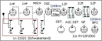
Ln21021 Schwabenland (Luftwaffe
version, Marine version is
EO 8268)
ZF 1240kHz, 1,5-25MHz in 8 bands, 11x RV12P2000 STV150/20 Te30
BFO: 1241kHz,
HF, HF, Mix, Osz, ZF, ZF, ZF, Diode, AGC-diode, NF, BFO
Note that it used 2x RV12P2000 for 2 diode functions, where
Mw.E.c and Köln E52 would use single valve for 3 functions,
T9K39 uses 1x RV12P2000 as a rectifier diode. Both Ln21021/E=8268
and T9K39 has no audio input amplifier.
Geräte Handbuch: D.(Luft) T.4415 -
available from Fritz Trenkle.
See picture at http://www.laud.no/la6nca/staaland/index.htm
Lo1UK35
(SE 42444/c)
UK-Marine-Tornistergerät
(41,55-45,75MHz)
0,6-0,7W
See
more specific info and measurements for the receiver on page 25h
Lo6K39 (Lorenz) (the receiver looks exactly like
Lo6L39) Reg. RX type: 3V1
Ranges: 1.45-2.2, 2.07-3.14, 2.96-4.46, 4.2-6.35, 5.97-9,
8.48-12.77, 12.030-18.13, 17.07-25.75MHz
Circuit: 6x RV12P2000, STV150/20, TE30, 12V 5W dial lamp.
1.RF, 2.RF, 3.RF, Audion-detector, Audio amplfier, Calibrator.
Measures: 438H x 500W x 320D (mm)
Mains operated.
See
more specific info and measurements for the receiver on page 24l
|
 |
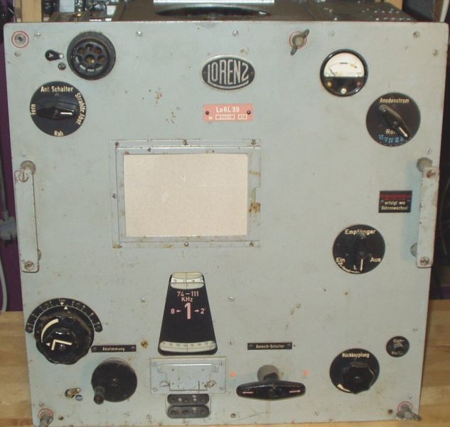
Lo6L39 (Lorenz) (the receiver looks exactly like
Lo6K39) Reg. RX type: 3V1
Ranges 74-111, 107-161, 156-235, 227-342, 330-497,
479-725, 697-1055, 1015-1530kHz
Circuit: 6x RV12P2000, STV150/20, TE30, 12V 5W dial lamp
(Sofittenlampe)
Power: 220V A.C 0.13A, 110V AC 0.26A
Measures: 438Height x 500Width x 320mm deep, weight 65kg
Mains operated.
See
more specific info and measurements for the receiver on page 24l
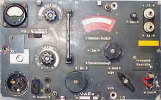
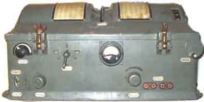
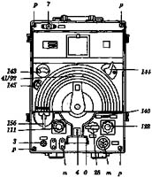
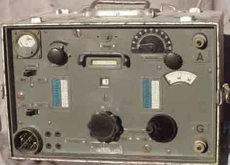
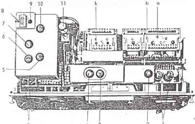
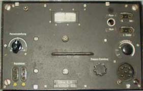
Mw.E.c
Ranges: 830-1600,
1600-3000kHz
Circuit: 9x RV12P2000
1. RF amplifier, 2. Mixer, 3. LO, 4. IF, 5. IF, 6. Signal and AGC
detectors + audio amplifier,
7-8. push-pull output stage, 9. BFO
An earlier version has two RF amplifiers.
IF: 352kHz, BFO: 353kHz.
DC power requirement: +12V 1.2A, +150V 30mA
Height 200mm, Width 313mm, Depth 180mm. Weight 13kg.
Dynamotor for 12V operation: EU.a, EU.a1, EU.a2, EU.a3, EU.a4
|
|
Mw.E.c vs EZ6
See
more specific info and measurement for the receiver on page 24b
Radione R3
Frequency range:
2.5-25.7MHz
Sensitivity: 5-10µV A1, 1-2µV A3.
Circuit:
EF13 RF
ECH11 MIX/Osz.
EF12 IF
EBC11 Detector/audio
EBC11 BFO
EDD11 Audio output.
IF=460kHz
Operating voltages: 120, 150, 190 or 220V AC, or 6, 12, or 24V
DC. 30W.
Measures: 24cm H x 35cm W x 17.5cm deep. Weight 11kg.
See
more specific info Radione receivers on page 25r
RP19 Kurzwellen-Abhorchgerät, Ostmarkwerk (Prag-Gbell)
[ D979/28]
Ranges: 1150-1850, 1700-2750kHz, 2,7-4,2, 3,9-6,3, 6-10,
9,5-15,5MHz
RP20 Langwellen-Abhorchgerät, Ostmarkwerk (Prag-Gbell)
[ D979/27]
Ranges: 15-22, 22-50, 50-120, 120-300, 250-575, 550-1250kHz
 |
 |
Torn E.b/24b-305, RX type: 2V1
Frquency range:
96- 7095kHz
Circuit: 4x RV2P800 as RF, RF, Detector, Audio output
(with audio filter)
Power requirement: 2V 0.8A, 90V 10mA. Automatic bias from anode
current.
Power supplies. EW.b and WS(E)b for 2V, EW.c, EW.c1 and WS(E)c/c1
for 12V.
See
more specific info and measurement for the receiver on page 22a
Torn.E. Spez445 Bs and 445b Bs, Reg.
RX type: 1V2
Frequency range:
950-3050kHz
Circuit. 4x RE074: RF, Audion, Audio, Audio (Audio filter)
Supply: Anode voltage 90V, filament 3.8V, -3V bias voltage.
T8PL39
"Martin" (E491 N)
This is a DF receiver, in-spite of that what the front looks
like, the chassis looks very
much like Lw.E.a. and (Kw.E.a)
The circuit diagram is very much like Lw.E.a, but the valves are
RV12P2000.
It has a 4-section tuning capacitor. Two tuned circuits ahead of
the RF amplifier.
 |
|
T8PL39 versus Lw.E.a
T8PL39 Circuit:
RF-amplifier, Mixer, Local Osc., 1st and 2nd IF-amplifiers,
Detector and audio amp.
(diode/triode connected valve), BFO/CAL, Audio output. The
detector/audio amplifier
is very much like E52, but it is no AGC detector. It is two
double tuned IF
bandpassfilters for the selectivity.
Frequency ranges:
I 72,5-119kHz
II 119,0-196kHz
III 196-321kHz
IV 321-527kHz
V 527-860kHz
IF= 60,9kHz
BFO: 60/61,8kHz.
Valves: 8x RV12P2000, Stabilovolt STV75/15 II, Te30
(Osram)
Osram 3766, 6418 and 57.7130 lamps
Sensitivity:
BW Pos 1-5. emission A1A 1-5µV
BW pos.1 emission A2A 5-20µV
Selectivity (3dB bandwidth): 5 steps 300Hz...8kHz.
Band I 1kHz, Band II 1,2kHz, Band III 1,5kHz, Band IV 3kHz, Band
V 3,5kHz.
IF rejection: Band I minimum 80dB =10E-6 (87kHz)
Image rejection: At 400kHz 10E-6, 200kHz 2*10E-6, 120kHz
4*10E-6
See
more specific info for the receiver on page 22c
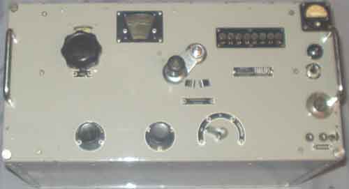
T9K39
'Main' (Telefunken)
|
|
T9K39 vs Köln E52b
Ranges: 1.5-2.4,
2.4-3.8, 3.8-5.9, 5.9-8.7, 8.7-12.5, 12.5-16.4, 16.4-20.6,
20.6-25MHz
IF=730kHz, xtal filter
IF selectivity: 100-5000Hz variable
Sensitivity on 4615kHz: 0.5µV with lowest selectivity for
10dB S/N on A1A.
2µV for 5kHz bandwidth. on A1A for 10dB S/N.
6µV for A2A, A3 for 10dB S/N.
Circuit:
1.RF RV12P2001
2.RF RV12P2001
3.RF RV12P2001
MIX RV12P2000
LO RV12P2000
1.IF RV12P2001
2.IF RV12P2000
Diode det RV12P2000
Audio RV12P2000
BFO RV12P2000
STV100/25Z, TE30, 2x 6V 7.5W dial lamps
Antenna impedance 150 ohm balanced or unbalanced.
Blocking: Withstand 200V for normal reception when operating on
4615kHz.
Audio output: 10V for headphone (4000ohm) and 1V for
Hellschreiber or audio amplifier.
Mains powered (75, 110, 150 or 220V V AC 50Hz, 100VA).
Ua=200V 50mA, Uh=12.6V 0,7A, grid voltage -18V.
Measures: 550W x 295H x 330mm deep.
Weight: 44kg
Further info: Anlagen-Kennblatt Nr. A202
Ûberlagerungsempfänger T9K39 (Main) - Kriegsmarine
DF Unit, see: Peilvorsatz
"Preßkohle 2" für KW-Empfänger "Main" (PKZ/M = Telefunken PV187 M1/43).
See
more specific info and measurement for the receiver on page 24m
Torn.Fu.b1, Torn.Fu.c
Torn.Fuf
| Gerät | Frequenz-Bereich |
| Torn.Fu.b1 Empfänger | 3,0-6,6MHz (RX)................ZF: 2.0MHz |
| Torn.Fu.b1 Sender | 3,0-5,0MHz (TX) |
| Torn.Fu.c Empfänger | 1,5-2,6MHz (RX).................ZF: 2.0MHz |
| Torn.Fu.c Sender | 1,5-2,3MHz (TX) |
| Torn.Fu.f Empfänger | 3,0-6,6MHz (RX).................ZF: 2.0MHz |
| Torn.Fu.f Sender | 4,5-6,6MHz (TX) |
See
more specific info and measurements for the receiver on page 25a
Spez. 801 (Gr.2/37) [Telefunken]
Frequency ranges:
1460-2250, 2080-3190, 2940-4450, 4230-6540, 6000-9240,
8450-13000, 11500-17650, 15000-23000kHz.
Circuit:
1.RF RENS1284 (indirect heated)
2.RF RES094 (direct heated)
MIX/OSC ACH1 Gr (indirect heated)
1.IF RES094
2.IF RES094
3.IF RES094
Detector/BFO ACH1 Gr.
Audio output RE134 (direct heated)
IF amplifier for AGC RES094
AGC detector (voltage doubler) Sirutor (dry
diodes)
Sensitivity: 0.4-1µV for A1 and 1-10µV to achieve 4V
audio output voltage with 4000 ohm load.
"Spulenrevolver".
Variable feedback in IF to improve selectivity (Q-multiplier).
Later version has RF-gain omitted and as such probably not
suitable for SSB although it has
"product-detector". AGC detector is early version of
the type found in Kw.E.a
Audio outputs: 4000 ohm for headphones, and 600 ohm for
telephone cable application.
Power requirement: 4V 1.5A (H1), 4V 2A (H2), 100V 15mA, 150V
25mA. Grid voltages: -1.5, -7, -6V.
Power supply unit: EN401 Rö.
See
more specific info and measurements for the receiver on page 17t
See AGC and detector notes on page f13
UKW.E.d1, see more info here
Ukw.E.e (see also Ukw.E.h). (Matching
transmitter: 10W.S.c)
Frequency range 27.2-33.2MHz
(UkwEh: 24.1-28.0MHz)
performance data has not been seen for these receivers.
7x RV12P4000 (a rugged version of RV12P2000) as
RF, MIX, LO, IF, IF, Diode, Audio output (intercom).
IF=3.0MHz , AM only.
"Gelbstrich"-geräte (=Yellow marked equipment):
Modification for intercom.
Dynamotor for 12V operation: EU.a, EU.a1, EU.a2, EU.a3, EU.a4
Circuit diagram is shown on page 901
See
more specific info and measurements for the receiver on page 24t
|
 |
Ukw.E.h
Frequency range: 24.1-28.0MHz.
Same circuit as for Ukw.E.e
"Gelbstrich"-geräte
(=Yellow marked equipment): Modification for intercom.
See
more specific info and measurements for the receiver on page 24t
Wehrmacht Rundfunkempfänger
WR 1/T (Telefunken),
IF=468kHz
Long-/Medium/Shortwave bands
Valves: DCH11, 2x DF11, DAF11, DC11, DDD11 and DAF11 as mike
amplifier
see also WR 1/P (Philips): DCH25, 2x DF25, DAC25, DC25, DDD25,
and DF26 as mike amplifier
IF=468kHz
WR 2: DCH11, 2x DF11, DAF11, DL11
Feldfernschreiber
(Hellschreiber) 24a-32, see circuit diagrams on page 901
For further information, see http://www.qsl.net/zl1bpu/FUZZY/History/History.html
Note: Sirutor 5b and similar
small-signal rectifier diodes found in different receivers (EZ-6,
Fu.H.E.c,
Kw.E.a etc) are usually defective measuring 1k in one direction
and 5...10k in opposite.
They need to be repaired mounting a 1N4148 or AA118
(1N34A) diode inside the tube,
use IN4148 for AGC circuits (KwEa and FuHEc) and for E52 (noise
limiter), germanium for EZ6..
Substitute valve for RE074: 1H4 (octal base) has
equak data, but 1.4V filament
Substitute valve type to repair a RV2P800: 5678, CV2254, XFR2, DF60.
Reference book for accessories: Zubehör für
Wehrmachtsfunkgeräte
(Reinhard Helsper).
RT-77 (AN/GRC-9) Ranges 2.0-3.6, 3.6-6.6, 6.6-12MHz. RX:
IF=456kHz, BFO 228kHz
Dynamotor DY-88/GRC-9-GY. Generator GN-58-A-GY
See further info on pg-f11 and 61
 |
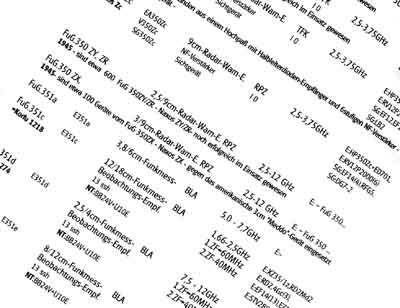 |
Can you really do without it?
Kommerzielle Nachrichtengeräte
von 1914-1945 (DL2IE, Gerhard B. Salzmann)
Sourcebook for investigating into the
material mentioned above, and much more.
No serious collector can do without this book! It is available from DL6VW Werner Gierlach
A good source for exploring possibilities using old valves is
Receiver Topics chapter of Pat Hawker G3VA's
"Amateur
Radio Techniques" Sixth
edition 1977. Radio Society of Great Britain. The book also
contains IF-tables.
Some other very useful books to look for are:
Surplus Radio Conversion Manual.
At least 4 different volumes were
published between 1948-1960. Although some advice given is
inapplicable today, several circuit diagrams, drawings
and instructions are very valuable for many different American
surplus sets. British sets are described in PA0CPR
Louis Meulstee's 3 volumes of Wireless for the Warrior.
Martin Streetley's: Confound&Destroy
ISBN 0 7106 0356 8
is another valuable book although it doesn't show any circuit
diagrams, but it shows very much different equipment,
German and allied, and also includes aircrafts.
Fred Osterman: Shortwave Receivers - past & present is a valuable book,
too, particularly for post-war receivers, but covers not too much
European equipment. ISBN 1-882123-07-7.
A small book which seems to be overlooked by collectors, but
available from Werner Gierlach is Reinhard Helsper's:
Zubehör für
Wehrmachtsfunkgeräte. It contains information for
crystals, power converters (dynamotors),
vibrators, diesel aggregates, and accessories (It is written in
1994)..

Last update: 2005.01.09