
23g. Polish WW2 radio equipment (RX) Radiostacja N1, N2
Other similar pages:
e11
Receiver's Intermediate Frequency List - 1
e13
Receiver's Intermediate Frequency List - 2
e12
Data for German communication receivers
17s Tfk
E381S
17t Tfk
Spez.801
AQ2/3
(=N1) Radio station.
Receiver AQ was a part of military
radio station N1. This station was designed for use in
communication vans (N1S) or horse vehicles (N1T).
Made by Panstwowe Zaklady Tele- i Radiotechniczne (PZT or PZTiR)
in Warsaw since 1938 and by Germans in the same factory
during WW II.
170 pcs were made before September 1939. Seen by Polish officers
in Western Europe in 1944.
AQ is original symbol of that set.
Frequency coverage: 2250-6750 kHz.
Modes: CW, MCW, AM. Power: 90 W on CW, 65 W on AM.
Weight: 70 kg. Antenna: 9 m telescopic, 3,5 or 6 m whip (wire in
bamboo), random wire 9 m. Operated by a crew 4-5 men.
Station N1 consisted of a transmitter and two receivers -
main and auxiliary.
The main receiver (6-valves superhet) and the transmitter were
inserted in one wooden box. The receiver of radio station N2 was
the auxiliary receiver of radio station N1.
There is a manual of radio station N2 in Central Military Library
(CBW) in Warsaw. I was there two weeks ago and they are making
for me copies. I hope I will get them in 1 or 2 months and
then I will sent them to you. <Roman Buja>
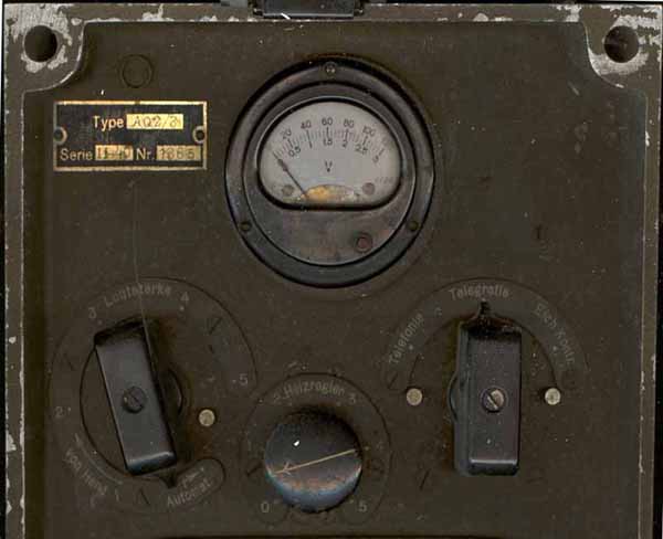
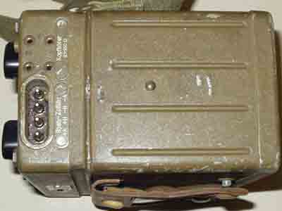
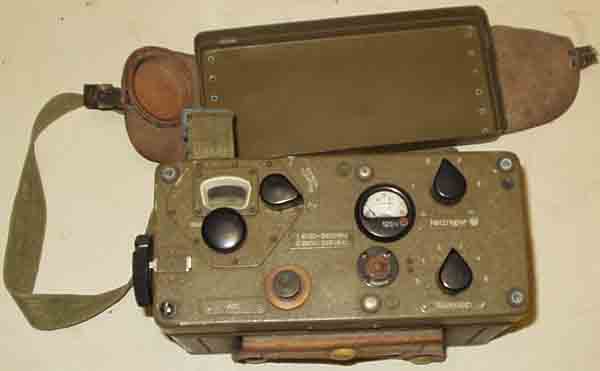
The AQ2/3 receiver seen from different angles:
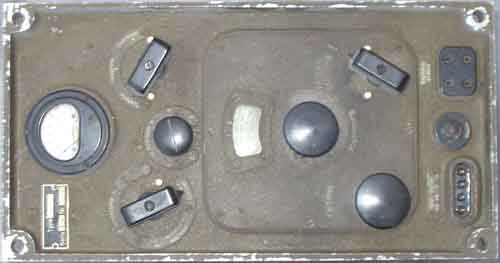 Front |
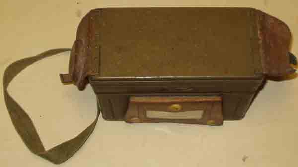
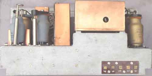 Rear side |
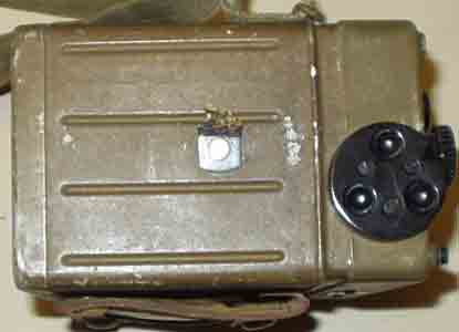
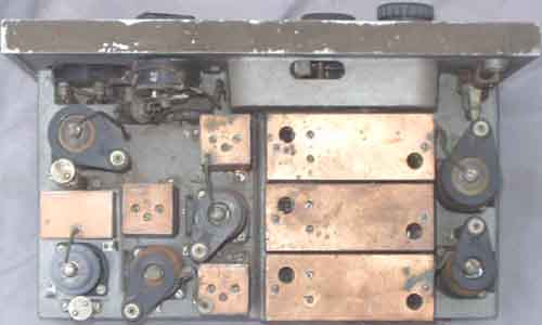 Overside (BFO screen cover is removed) |
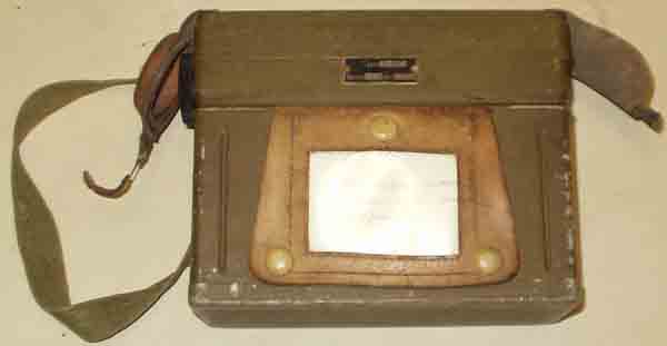
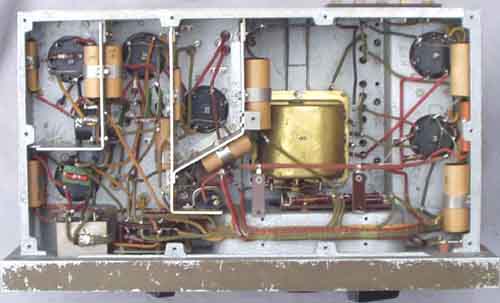 Underside |
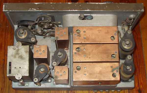
Seen from above (w/BFO screen)
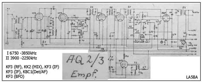 |
AQ2/3 RX circuit diagram which was drawn on the wall at Sola Airport
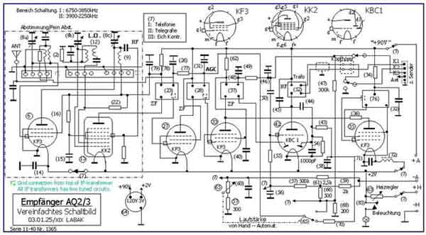 |
My own circuit
diagram for AQ2/3 RX
Odbiornik N2 wz. 37
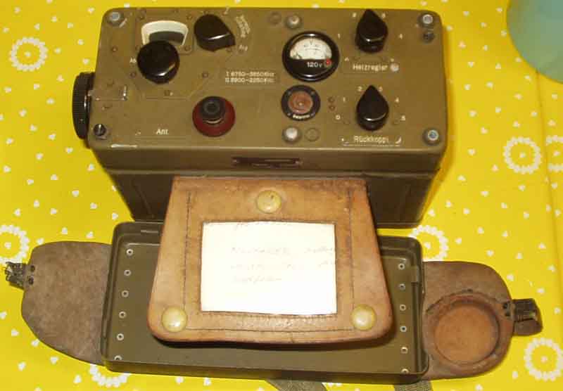
Receiver of Polish
radio station N2 (AQ2/4).
Some details: Made by PZTiR
between 1937 and 1939 and by Germans in the same factory
during WW II. 1019 pcs were made to Polish Army. It was universal
battalion station.
Versions:
N2S - used in cars (FIAT 508/518),
N2T - used in horse vehicles,
N2B - used in artillery,
N2L - used in airplanes
(fighters),
N2C - used in armoured vehicles
(tank 7TP).
Frequency coverage: 2250-6750 kHz.
Mode: AM, CW. Power: AM - 2 W, CW - 6 W.
Antennas: 2,5, 3,5 and 6 m whip (wire in bamboo) and 8 m random
wire.
Range: 6 m whip - 10 km on AM and 25 km on CW. Weight: 50 kg.
Transmitter: 2 valves - Marconi
DET 9x, Philips PC 05/15.
Receiver: 4 valves (superhet) - 1 x KK 2, 3 x KF 4. Sensitivity:
14 uV. N2 has contained 2
such receivers.
Receiver N2 was also auxiliary receiver in N1 radio station (see
photos of N1).
The main constructor of N1 and N2 radio stations was eng. Henryk
Magnuski who has designed the American SCR-300 FM
"Walkie-Talkie".
Fritz Trenkle books and another
publications on German equipment has no info for N1 (AQ2) and N2
Polish stations.
There are no such radio station and receiver in Polish museums
and in private collections.
<Roman Buja>
 |
 |
 |
 |
 |
 |
 |
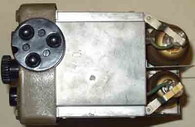 |
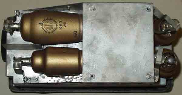
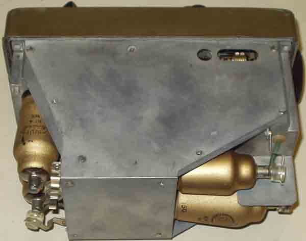
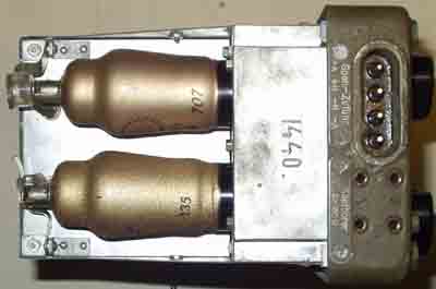
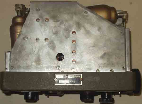
AQ2/4 receiver, seen from different sides
N2 receiver, valves: KF4 (RF amplifier), KK2 (mixer/local osc),
KF4 (IF/detector), KF4 (audio amplifier),
note the bandswitching
switch.
Somewhat more readable circuit diagram for the receiver
[Odbiornik N2 wz. 37]
N2 transmitter; 2 valves - Marconi DET 9x, Philips PC 05/15.
4,6V 1,2A, 15V 150mA, +420V 65mA
Somewhat better readable circuit diagram for the transmitter
[Nadajnik N2 wz. 37], tnx to Roman Buja.
See page f21 for component info.
See more rig-info on Radiostacja
N1 (Piotr Krzysztofik SQ7HGP http://www.rkd.friko.pl/ ) or better at http://www.radioam.net/sq7hgp/polska.html
Last update 2005.03.07