24t)
Radio-communication equipment
Ukw.E.c1, Ukw.E.d1, Ukw.E.e, Ukw.E.h
Similar pages:
e11.
Receiver's Intermediate Frequency List
e12.
Data for German communication receivers
e86.
Thermionic Valves (tubes)
28a.
Rotary converters
30g.
10WSc, 20W.S.d
Items moved to another
page:
Wetter-Sonde, see page e67
Blindflug-Leitstrahl-Anlage
E Bl 3, see page 24z
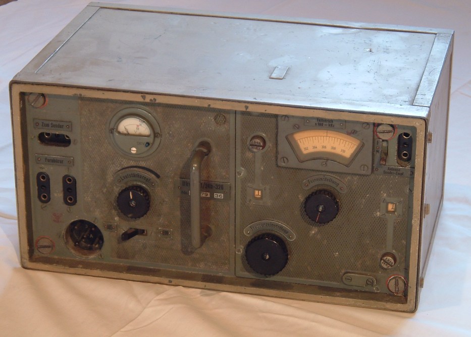
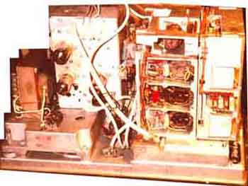
UKWEc1 10m receiver (27,2-33,2MHz)
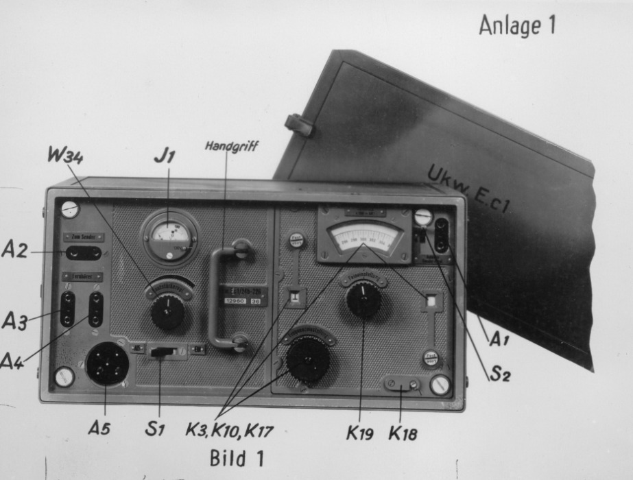
Foto1_handbuch
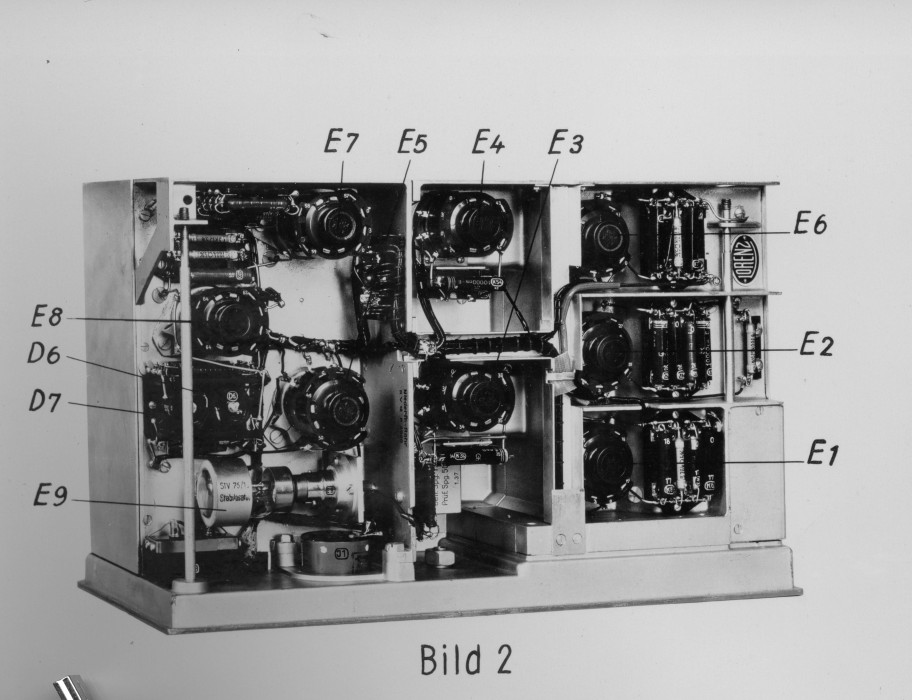
foto2
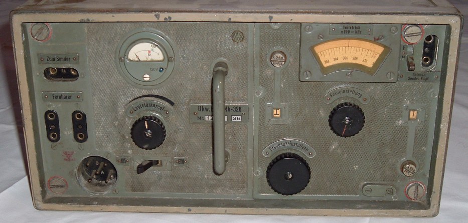
front
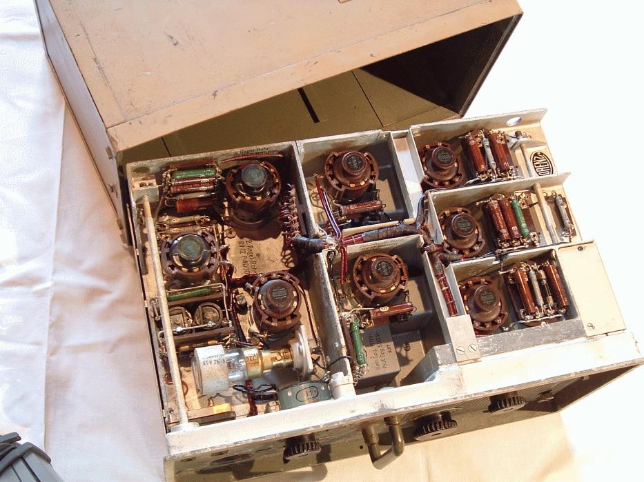
Innen/oben
Ukw.E.c1 circuit diagrams on page 906
tnx Werner DB7EW http://www.radiomuseum.org/dsp_profile.cfm?member_id=3242
Ukw.E.d (1937) 42.1-47.7MHz, IF=3.1MHz
Ukw.E.d1 42.1-47.7MHz
Ukw.E.d1 42.1-47.7MHz - somewhat modified
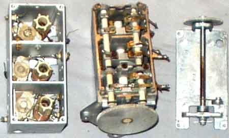
Ukw.E.e.: RF coils and tuning capacitor with the
bandspread section on the right side (from an experiment in 1970)
Matching
transmitter is 10W.S.c, more information
| Frequency range | matching transmitter | |
| Ukw.E.e | 27,2-33,2MHz | 10W.S.c |
| Ukw.E.h | 24,1-28,0MHz | 10 W.S.h |
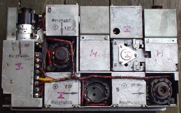
Performance data has
not been seen for these receivers. Circuit: 7x RV12P4000
(a rugged version of RV12P2000) as RF, MIX, LO, IF, IF, Diode,
Audio output (intercom).
IF=3.0MHz , AM only.
"Gelbstrich"-geräte (=Yellow marked equipment):
Modification for intercom.
Dynamotor for 12V operation: EU.a, EU.a1, EU.a2, EU.a3, EU.a4
Audio output transformer: 6600(1650W)/2200T(250W DC),
turns ratio 3:1.
Ukw.E.h covers 23,0-24,95MHz
(divided into 40 Channels per 50kHz, channel #241-280).
Ukw.E.c1 (by LORENZ) same frequency
range as Ukw.E.e IF is shown
as 3100kHz in its documentation.
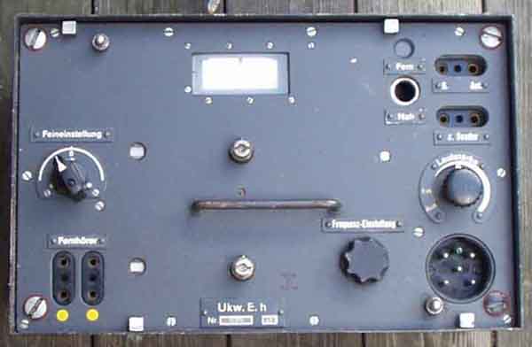
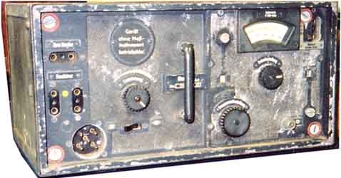
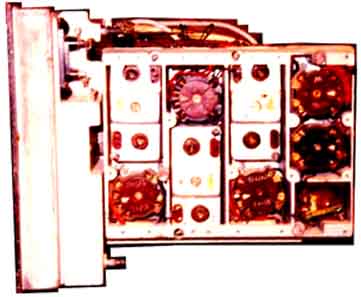
Ukw.E.h receiver (24,1-28,0MHz)
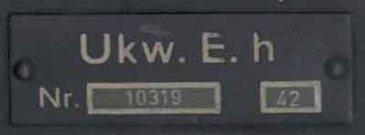
Type mark
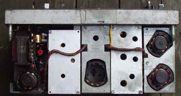
Receiver seen from above
Receiver seen from rear
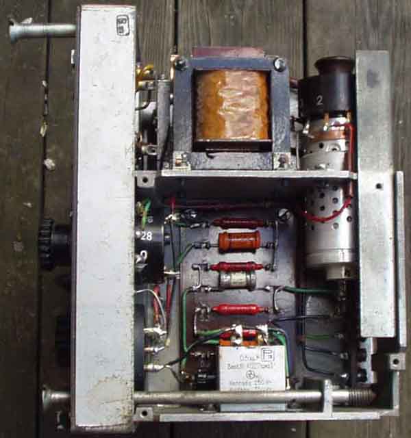
Audio amplifier and dc power input stage seen from the side
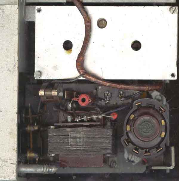
Audio amplifier seen from above, audio output valve and
transformer easily seen with the neon stabilizer tube clamp at
center left
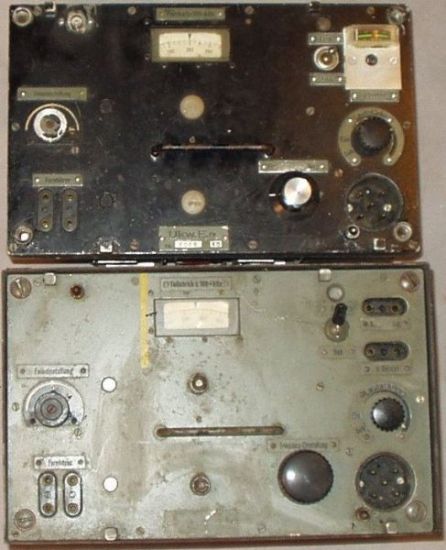
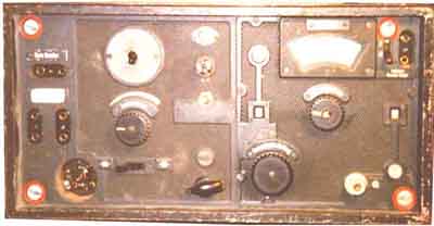
Two Ukw.E.e, somewhat modified or missing details. The third item
misses the power connector. But they have been extensively used
in amateur radio until the 1970's on 28MHz with 2m converters and
perhaps this is the reason they still exist. It is more important
to keep them operationable than keeping all original details.
For Ukw.E.e and Ukw.E.h circuit diagram, see pg 901
If you want to use UkwEe/UkwEh on amateur bands - where most
current traffic is in SSB and CW modes, you will learn that the
beat note isn't clean. The reaons for this is that the sawtooth
wave from the neon lamp noise modulates the local oscillator. A
way out of this is the so-called "Drake TR-4" solution
where an extra diode is added, this is in fact an alternative to
the two-anode type of stabilizer used in Germany before the war.
For further decoupling it is adviced to use two diodes as shown.
Without these diodes it is not possible to decouple the
stabilized voltage, the neon lamp will flash bright and soon be
damaged, but with the extra diodes it is no more load on the
neonlamp, and possible to have a clean output voltage at the
average level.
It seems easiest to mount the extra components on the connector.
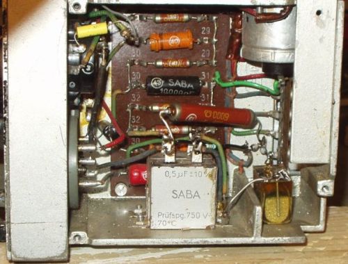
Seen in the bottom right corner, the 8000 ohm resistor is moved
from above to under chassis. The 0,5µF capacitor shortcircuited
after less than 5 minutes, it is the wellknown bad type of paper
capacitor.
RV12P4000 (same size as RL2P3)
Power connection. Believe the +Umf can be used to check the
heater voltage inside the receiver from the power supply and
switch on some external equipment when the receiver is in use.
Aktuelle artikler å sjekke opp
(Some Norwegian language articles to mention):
UKw.E.e Mottaker 27-30MHz - Skjema .................... AR
71-03-053
RV12P2000 og RV12P2001 brukes i nyeste mottakere AR 51-09-246

last update 2005.04.11