
Kw.E.a - HF
communication receiver
(manufactured from
1938/39++)
Front view differences with Lw.E.a
Links to reference pages:
e11. Receiver's
Intermediate Frequency List
e12. Data for German
communication receivers
e86 Thermionic Valves
(tubes)
22a Torn.E.b
22r SSB for KwEa
22c LwEa and T8PL39
22h)
Funkhorchempfänger 'c' und 'u', Fu.H.Ec and Fu.H.E.u
28b EWb and EWc DC-DC
inverters
28c NA6, NA6a
Netzanschlussgerät für KwEa und LwEa
E96 Netzgeräte für
KwEa, LwEa, Torn.E.b, FuHEc, FuHEu
Technical articles under preparation (received from PA0SE Dick
Rollema):
10a Introduction to German World War II Radio Equipment
12a. German World War II Radio Equipment - Köln E52
receiver - part 1 (PA0SE Dick Rolema)
12b. German World War II Radio Equipment - Köln E52
receiver - part 2 (PA0SE Dick Rolema)
12c. Lorenz Shortwave Receiver Lo6K39a (Lo6L39), The
ultimate TRF set [PA0SE]
12d. Telefunken World
War II Superheterodyne Receiver Kw.E.a (Lw.E.a) [PA0SE]
10b. Telefunken World War II Universal TRF receiver
Torn.E.b [PA0SE]
 |
 |
Electrical
differences with Lw.E.a
More info for Kwea/E454Bs and LwEa/E440Bs
Circuit diagram for KwEa as pdf file is available here (tnx
LA6TJA):
/la8ak/12345/images/KwEa_dia.pdf (874kB)
These additional scanned files from the handbook are available
upon request:
pg 1-7 (2174kB), pg 8-19 (2175kB), pg 20-36 (2183kB), pg37-38
(268kB)
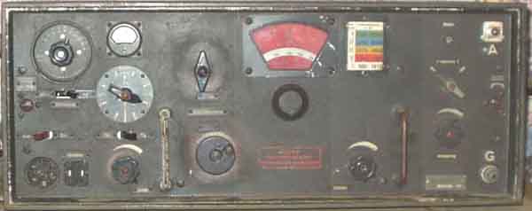
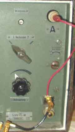
Front view
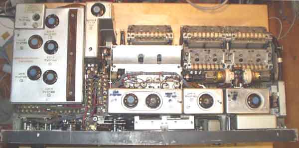
The receiver seen from above
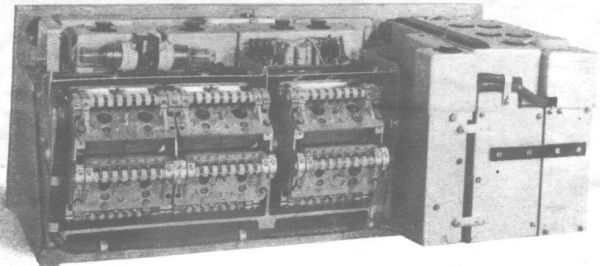
The receiver seen from the
rear (picture from the handbook)
 |
 |
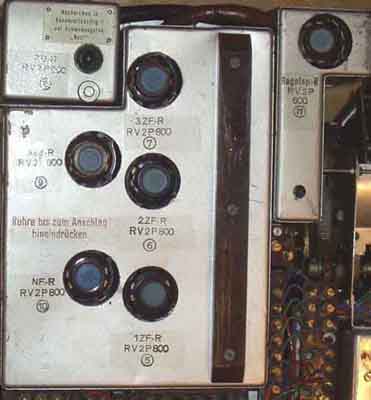
Differences in IF-section between KwEa and LwEa
This receiver has 3 IF stages, and an extra AGC amplifier, while
LwEa has only two IF stages and no AGC.
Optimizing the receiver or not (SSB):
The first thing to do when you have unscrewed the front and have
done some possible repair*), is to rewire the
RF gain (Störhöhe) such that it operates independent for CW/SSB
reception. This is more important if you don't
improve it for SSB in other way as mentioned below. The reason is
that since the BFO injection is so weak you
must decrease the RF gain to avoid overloading the detector
process, and you must increase the audio gain
by the same amount. It is not possible without this rewiring.
NOTE: It should be mentioned that neither any of my
Kw.E.a's nor Lw.E.a have needed any sort of repair,
no capacitors have been found defective in any way. But this may
not indicate that they are not bad in
any ways, they just work satisfactorily. Got the 2nd
KwEa from LA1JC as a present in 1967, the first was purchased
from LA1II (later Permo) in 1963, and unfortunately sold in
1968..
See further SSB modification
notes on page
22r
The AGC amplifier is in principle - very much the
same circuit as for Collins 51-S. A standard voltage doubler is
used with a voltage delay of +3,5V so that the AGC level
increases faster when it reaches a certain level, but let weaker
signal pass without attenuation. The Collins receiver doesn't
have different time-constants for different modes, the
modifications are shown on page b35, and
the improvement was tremendous, and the Collins 51S was designed
20 years later than KwEa! Even BC-348 has different time
constants for the different modes.
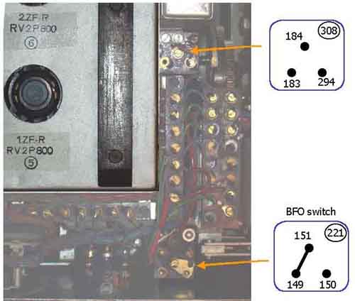
On board "308" one may choose between 0,1 and 2µF in
Telegraphy mode, dependent on whether the receiver operates for
"bewegl. - (= mobile)" or "stat.
Betrieb (= stationary operation)", but it is a similary
selector mentioned on the circuit diagram for E52 'Köln', see
the next note below.
AGC measurements
[frequency 2200kHz, Bandwidth pos.2, Vorkreise '1', Wavetek Model
3001, WG SPM-3 Pegelmesser (high impedance), AF load 4000 ohm].
RF gain turned up fully clockwise, AF gain adjusted to desired
output level.
| RF level | Audio output level |
| 3µV | +4dBU |
| 10µV | +12dBU |
| 30µV | +12,5dBU |
| 100µV | +14dBU |
| 300µV | +14,5dBm |
| 1mV | +15dBm |
| 3mV | +15,5dBm |
| 10mV | +15,5dBm |
| 30mV | +16dBm |
| 100mV | +17dBm |
| 300mV | +17,8dBm |
The RF gain control (Störhöhe) has no or little (less than
1dB) effect on AF level over the range for RF levels above 100mV
pd.
Background noise (for the AF gain setting): -14dBU. [AGC
threshold at ca.18-20dB SINAD]
Blockdiagram showing which stages have AGC and which have MGC,
from the above notes it seems that MGC has somewhat less than
desired regulation, while AGC range is almost what is expected
from a good communication receiver. Note that I have modified the
receiver such that RF gain control is independent of audio level
control setting, it is otherwise a problem to receive ssb
signals.
The AGC amplifier for Collins 51S is functionally very similar to
Kw.E.a
 |
 |
1) Antenna connection for
coax cable with LwEa and KwEa receivers.
2) Function selectors inside this receiver.
"221": It is possible to decide that BFO
is activated when bandwidth positions 6-8 are chosen,
and the normal BFO switch is disabled (I don't know any
expression for this selector).
"308" Bewegl./stat.
Betrieb. The
handbook doesn't tell, the circuit diagrams are almost
unreadable, but it seems to be a possibility to increase the AGC
time constant with 2µF (304), and
according to the manual for Köln E52 to optimize the AGC (to
short time-constant) for mobile operation
(the words refers to notes in the E52 handbook).
 |
 |
AGC/MGC switch modification for SSB operation.
see the notes for E52-series receivers
One should consider the bias circuit when
building a power supply for the receiver, similar circuits for
LwEa, FuHEc, FuHEu, TornEb
A simple way to connect a loadspeaker to a German receiver using
loadspeaker transformer for 6BQ5/EL84 is shown on page.f16).
The result is quite good and satisfactory level even for SSB
reception when RF gain has been rewired and BFO level increased.
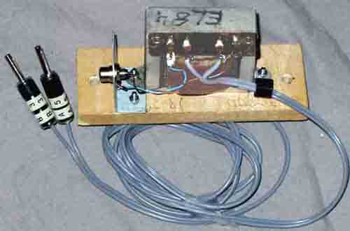
Audio level meter for the receiver.
The receiver miss an S-meter, but you can compensate for it with
an audio meter. It is fairly easy to make since the level is
quite high and diode type is not critical, so I used OA70 type
diode (but any germanium diode will do the job)
Technical information
Kurzwellenempfänger "Anton"
Ranges:
I .. 980-1610kHz .(Wht)
II 1560- 2550 .......(Red)
III 2470-4060 .......(Yel)
IV 3940- 6395 .......(Blu)
V.. 6205-10200...... (Grn)
Power supply: 2V accumulator and 90V anode battery or
Netzanschlussgerät
NA6/NA6a, EU.d converter for 12V supply
Filament supply 2V 2,2A
Anode supply 90V 20...25mA
Measures: Height 274mm, width 692mm, depth 346mm, weight
42kg
Acessories; 2 headphones Dfh.a, 5 core cable w/connectors for
supply voltages
Circuit: Valves: 11x RV2P800 as 2 RF amplifiers, mixer, 3
IF-amplifier, AGC IF amplifier and dry-diode detector (2x Sirutor
5b),
BFO/Calibrator (xtals 250/251,8kHz), Audion detector, Audio
amplifier.
2 neon type Telefunken Te30
 RV2P800 |
 Te30 |
Te30 are neon tubes,
110V ignition and 80V stabilized voltage for RF input protection, see
page e86 .
One or two tuned circuits ahead of first RF amplifier, two tuned
circuits
between first and second RF amplifier, and one between 2nd RF and
mixer
plus one section for local oscillator.
3 double-tuned IF amplifier circuits for variable selectivity.
Reduced IF level to detector for CW (with BFO). Audio filter for
selectivity position 5-7(8). Position 7 and 8 have equal
selectity
but BFO frequency is 251,8kHz for position 8.
Meter for anode currents and supply voltage.
Antenna: 200...500pF capacitance
Sensitivity for 1V RMS output into 4000 ohm,
single input circuit, without AGC:
| Ved telefoni | |
| Bølgeområde I...V | 3....5µV |
| Ved telegrafi: | |
| Bølgeområde I...IV | 0,5....2µV |
| Bølgeområde V | 1......2µV |
Selectivity:
| Selectivity: | Forstemning av målesender |
Fall i utgangsspenning ved konstant inngangsspenning |
||
| Bandwidth position |
Mode |
Offset signal |
Signal attenuation |
Voltage ratio |
| 1 | Telephony | 4-12kHz | 40dB | 100:1 |
| 2 | Telephony | 3-10kHz | 40dB | 100:1 |
| 3 | Telephony | 3-9kHz | 55dB | 500:1 |
| 4 | Telephony | 1,5-5kHz | 55dB | 500:1 |
| 7,8 | Telegraphy | 1,8kHz | 55dB | 500:1 |
Image rejection; at least 78dB
(8000:1) @10MHz.
Circuit notes:
RF and AF gain controls are normally combined when AGC is on, but
possible to
choose separate gain controls as without AGC with internal
selector (switch).
RF gain is achieved by varying the gain on certain RF/IF valves
with variable
screen grid voltage, but it is not the same valves as have AGC
applied.
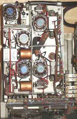
Intermediate Frequency filters.
It is three similar IF-stages on 250,9kHz. The circuit is drawn
such that the similarities/differences with LwEa and T8PL39
(60kHz IF) can be seen. (next page).
see page 28c for power supply
considerations using different equipment with NA6a
Current consumption: Filament current 2,2A, Anode current
20...25mA
Utførelse: Frontplate og chassis er støpt i silumin, kasse og
deksel av pansertre
Ytre mål: Høyde ca 274mm, bredde ca 692mm, dybde ca 346mm
Vekt: 42kg (med rør)
Tilbehør: 2stk hodetelefoner Dfh.a og 1stk 5-leder kabel med
5-polige kontakter for strømforsyning
 |
 |
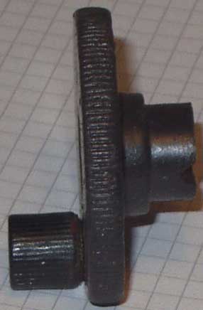 |
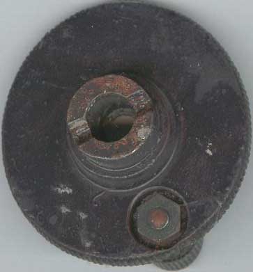
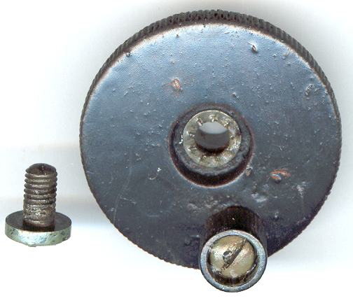
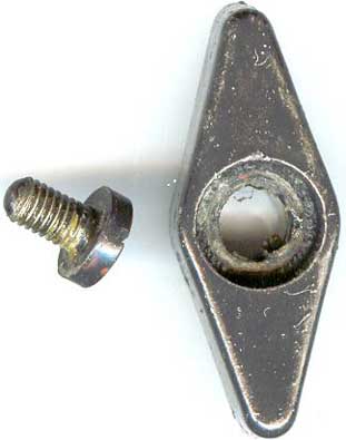
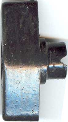
Constructing a tuning knob for KwEa or LwEa, see
page f21.
 |
 |
 |
Wavechange switch
M6 screw.

[D(Luft) T.4403]
Further
notes (Vörzer
Anmerkungen):
KwEa mit Sichtpeilzusatz, und Prinzip des Sichtpeilanlage
Fu Peil A70a
see:
Die deutschen Funkpeil- und -Horch-Verfahren bis 1945, pg 99:
Aus der Anlage 351
entstand eine ortsfeste Version für die Luftwaffe mit einem
speziell and das
Goniometer angepaßten Kw.E.a/apt. (2,5-6,4MHz) Super mit 11x
RV2P800 und Vorstufe AF100)
mit der Bezeichnung 351bF = Fu Peil A 70, deren Anzeige jedoch
noch nicht voll befriedigte.
Notes for LwEa, T8PL39 and
NA6 (+ still some for KwEa) are found on on 22c,
and you will also find PA0SE Dick Rollema's notes on page 12d (not quite ready)
KW-Adcock-Peilanlagen.
Aus der Anlage 351N entstand
eine ortsfeste Version für die Luftwaffe mit einem speziell an
das Goniometer angepaßtem KwEa/apt. (2,5-6,4MHz Super mit 11x
RV2P800 und HF Vorstufe AF100) mit der Bezeichnung 351bF = FuPeil
A70, deren Anzeige jedoch auch noch nicht voll bedriedigte. Sie
kam ab Anfang 1941 in wenigen Exemparen zum Einsatz, z.B. in
Catania (Sizilien) zur Überwachung des allierten Flugverkehrs
von und zur Insel Malta.
Fritz Trenkle: Die dt. Funkpeil- und
-Horch-Verfahren bis 1945, S.99.
E-MAIL
Correspondence: You may write in English or German, Danish
or Swedish, but I will reply in English (or Norwegian)
2005.02.10