
Devoted
entirely to Amateur radio
d7. General CW/SSB technik for 70cm and upwards
d6. 6m techniques
d2. 2m techniques
d21 Converting Magnetic
TU8062 (70cm transmitter)
d27 Evaluating NMT450 equipment for amateur radio purposes
d31 Constructing
VHF/UHF/SHF beacons
m11. Griddipmeters
for HF/VHF/UHF
m12. VSWR- and wattmeters
...
 |
 |
 |
 |
 |
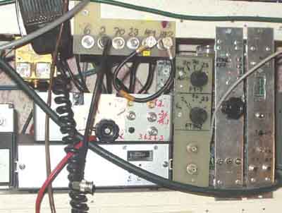
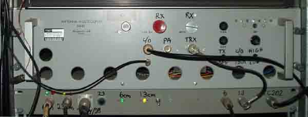
Panels for selection of RX-antenna/transverters, transceiver
keying/PTT, together with 136kHz
and 2m transverter
It is a good idea to put small power supplies in a separate empty
"rack module", possibly with lid.
+12V outputs for smaller equipment in the shack
1.0 General principles of
operation with remote VHF/UHF-transverter, power amplifier and
pre-amplifier
Principles for operation with transverter. Basic diagram for
remote controlled units
for 2m/70cm/23cm rigs. The following circuit diagrams are based
on this system,
but it is possible have some remote indication of failures or
manual blocking.
Remote PA may have a fault, or only cable for RX is connected.
Some decide to
use only single coax cable, but I wish to have the possibility to
listen on one band
when transmitting on another and have no problems finding
sufficient amount of
secondhand cables from work.
The use of +12v (shortcircuit proof) solves the problem with PTT
that a shortcircuit
to ground would otherwise cause the amplifier to switch on, while
in this case it
indicates a state of failure, which is indicated on an LED in the
shack.
1.1a
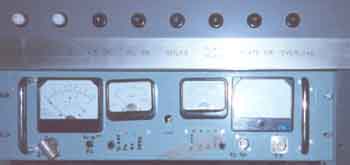
Pre-amplifier control-box for
2m and 70cm. Meters are cheap and directional couplers even
cheaper - to make.
So I've included a meter for each pre-amplifier (with remote
C/O-relays) and RF power output reading for each
band. Only small meters are needed for antenna-relay and pre-amp
current. The RF-indications may have delay or
direct reading, it is just a half LM358 to convert to peak
reading on whatever testpoint.
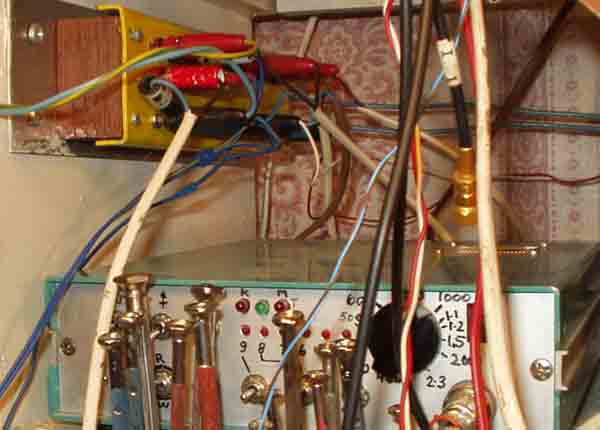
1.1b
Pre-amplifier control-box. It
is important that it is shortcircuit proof. If any faults occurs
such that the voltage does
not reach the remote pre-amplifier the relay switch to pass the
transmit signal to the antenna, and the pre-amplifier is
protected. The meter is not shown, but is connected over the 4.7W resistor.
Note that the TX-line is DC-shorted when the switch is in OFF
position. The transceiver or transverter senses this and
cannot operate, I use this function when PA is not switched on,
but only want to listen on the band. Since the equipment
is not in my shack, it is also meant as a signal that PA could
have a faulty condition and the transmitter should not be
able to send. Since it is only 1mW from FT-902 or FT-7 into the
transverter it is no problem and need not feed the signal
into the HF transceiver, but LED's on the transverter indicates
that the control box is disabled.
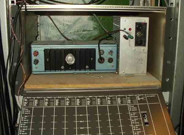
1.3
Here is my old rig selector
and transverter selector unit
tried to have the receivers through the unit, but crosstalk
between the different RX sides of transverters was a bad
problem, used small screened relays, but result was bad and I had
to revert to the BNC patch panel for receivers/-
antenna/transverters.
I use 14MHz IF for 6m, and 28MHz for 2m, 70cm, 23cm (and 144MHz
for 2320, 5760, 10368 and 24192MHz).
HF drive is from FT-7 or FT-902, and VHF drive is from IC202E.,
separate receivers: Drake 2-B and R-4C, with
FT-7 as spare transceiver.
The drive level from FT-7 and FT-902 are equal, as is the drive
from the 2m transverter and IC-202E, so it is not
much problem if one rig should fail, but I've really never had
such problem for over 30 years. Only had some xtal
oscillator problems with FT-250 (Yaesu), and no problem with any
other equipment for over 40 years.
1.4a
28MHz transverter remote control boxes used for 6m, 70cm, 23cm
operation. Indication for level, PTT-state and inhibit
1.4b
Simplified version transverter 28MHz remote control box. TX1 and
TX2 when transverters operates as normally,
while TX2 will not light when the remote part is inhibited
(manually or because of a remote fault).
1.5
VHF SSB/CW transverter with pre-amp and power amplifier. My
equipment is spread into two different rooms and
some provisions are made such I cannot transmit when the antenna
is not connected or the amplifier is not switched
on. The circuit diagram shows some signalling used for 6m, 2m,
70cm, 23cm band transverters to avoid damaging
the power devices when not all equipment are available
1.6a
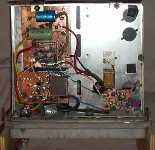
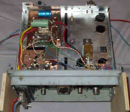
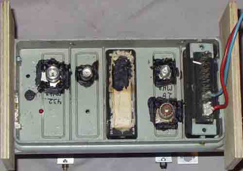
Microwave modules MMT432/28 component location
1.6b
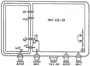
MMT432/28 external connections
 |
 |
 |
 |
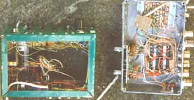
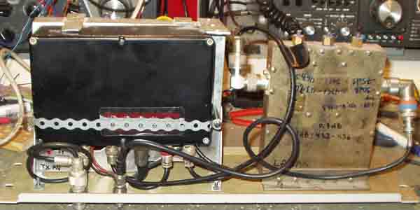
1.6c) Remote controlled Microwave transverter, mounted in Philips FTR box, it is very important that it is airtight. Have had a 2m pre-amplifier mounted in the antenna tower for 25 years in a similar box, so it is not difficult to do it right.
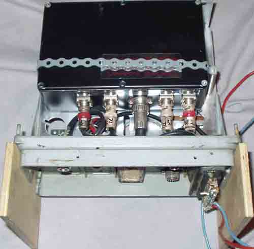
1.6d) MMT432/28 mounted on 19" panel
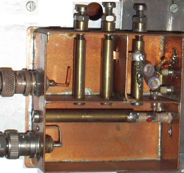
1.7
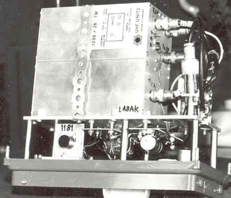
SHF Unit 23cm transverter built into FTR die cast box for
installation at the antenna.
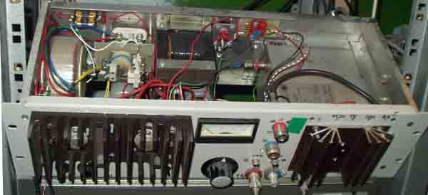
The rack-mounted transverter with 20W amplifier. The mechanical
construction is mainly a 13V power supply, 20W Mitsubishi
amplifier with cooling fin to the right and coax
through-connectors.
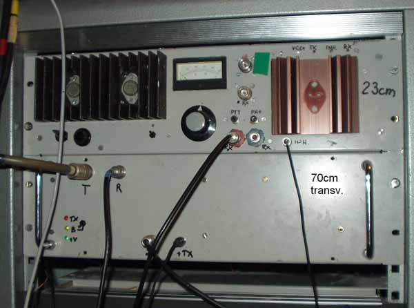
23 and 70cm transverters mounted into the 19" rack
1.8) 13cm rack mounted transverter with band-selector below
1.10
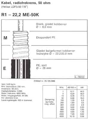
Heliax LDF5-50 7/8" coaxkabel
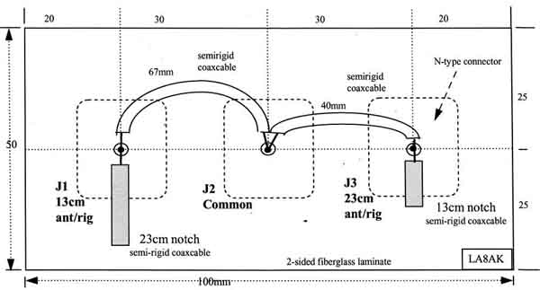
23/13cm antenna combiner (1296/2320MHz)
960322 LA8AK
383/1150MHz tripler for my planned 6cm
equipment made by SM6HYG around 1982
Still a useful book for finding VHF/UHF circuit diagrams and
components (SSB Electronics 1984, Componenten & Systeme)

2004.12.19