E97. Power supplies for German WW2 equipment
See the normal dc-dc inverters on page 28a and 28b, also
NA6a and NTG2 on 28c
Build your own mains power supply, see page e96, and
for 15W.S.E.a on page 31a
 |
 |
Helge
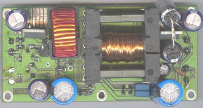
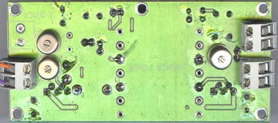
LA6NCA's 12V DC-DC mobile power supply unit for receivers and smaller transceivers
Output voltages:
Filament: +1.2....10VDC (regulated)
Anode voltage +60....150V (regulated) - galvanically insulated
from ground
Grid bias voltage 0....-10VDC (high impedance)
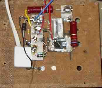
The PCB measures 100x43mm.
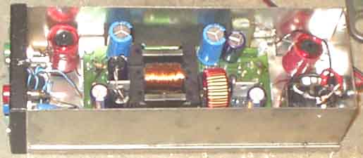
Earlier version of the DC/DC-converter. We
have forgotten the transformer winding details, and this version
is now discontinued.
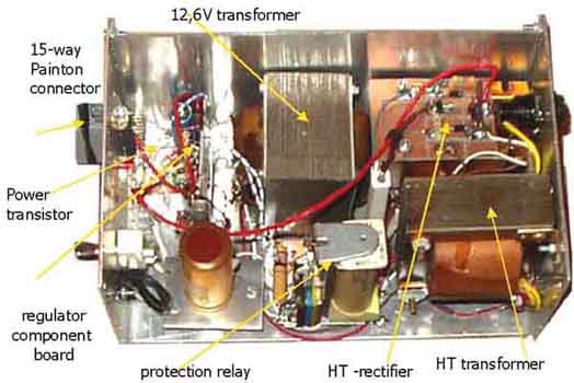
Helge's inverter mounted in a box - the way I want it - with some
extra noise filters and 12V input polarity protection relay (the
so-called PYE trick). It might be a good idea to add some fuses,
but you know, the constructions are usually decided during the
mechanical attempts, and another box was attempted first, but was
found too small. It is also an LED to indicate that the relay is
operated. Also connected a 10k resistor from minus-side of 100V
supply to ground, and 100k from positive side to ground to
decharge the capacitors. Minimum current for a receiver like
Torn.E.b is 10mA (on 90v) with -3V bias, so a 10K resistor hardly
changes the bias voltage.
The circuit diagram showing the external components. The relay is
any cheap type, but it is important that you check that it will
operate safe with 8V over the coil (to make room for supply
voltage variation).
The problem with this construction is that it is used SMD
components, and after assembling a douzen boards you are fed up,
it seems easier to use normal components, another problem is
interference. So a new version is under experiments, but it seems
not to be any problems with the filament supply, so the old
construction will be kept for this part. A 100Hz inverter using
conventional 50Hz transformers will be used in the next version,
with voltage control, and it seems to operate ufb.
With some more experience it was found desirable to add a 12V DC
output fed just from the input wire, to connect 12V heaters on
auxialliary equipment which could operate with the same HT+ as
the other equipment.
In one occassion it was problem
with interference via the filament voltage. It is quite easy to
make improvement. Since mainly dc current flows in the coil
toroid cores may have little effect for chokes where magnetizing
current may be somewhat high, ferrite cores with air-gap or
straight cores must be used here. For the 90V circuit toroid
cores may work provided that the current from positive and
negative side of the supply voltage have opposite magnetic
fields. A simple choke may be wound on a short piece of ferrite
core from ferrite antenna.
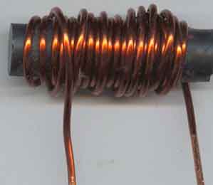
Winding 25 turns in 2 layers of 1.5mm enamelled copper wire on a
35mm long piece of 10mm diameter ferrite core (ferrite antenna)
is quite useful as choke, it has 27µH, and it has 17 ohm
impedance on 100kHz. So it is quite useful for filament circuit
with this inverter. But since you don't need so thick wire, 1mm
thick would be far more than you need, the impedance could easily
be increased to 35-50 ohm with the more proper wire.
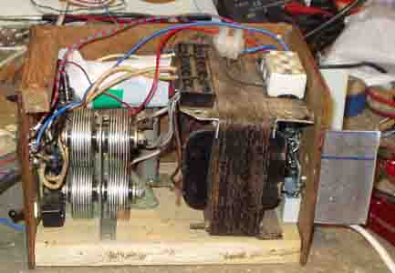
2nd DC/DC-inverter (+1.5...10V filament supply, +60...220V anode supply,
0...-10V grid bias).
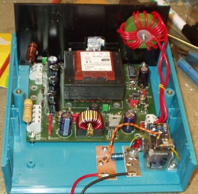
The latest LA6NCA power supply mounted in Pac Tec CM6-300 Kit
Electronic Enclosure.
To avoid winding the transformer, a standard type 110+110V
to 9+9V AC transformer for pcb mount is operated on
100Hz from push-pull mosfets with a 12V input DC-regulator. With
+12,2V input the output voltages may be varied in the region of
60...120V and 120...240V, dependent on whether one or two 110V
windings are chosen. The voltage regulation may be poor close to
the upper limit. I hooked up the polarity protection relay (RLA1)
and extra 12V input filter of choke (75µH - 10 turns - on toroid
core with air gap) and 22µF capacitor. The minimum current seems
to be around 300mA.
Idiot protection.
Everybody becomes idots, particularly in the field when it is
dark. Used a 12V 1,3kW relay for the input polarity proction, 4x2 contacts,
and to lower the operation voltage one section was disabled, the
operation voltage dropped to 9V. Since the relay shall operate
before current is drawn a small relay is sufficient, and all
systems are connected in paralell. An LED is mounted on the front
to indicate that the relay is operated.
Cooling arrangement.
With 12,2V DC input and 30mA load on 97V HT only a smaller
cooling fin (3x5cm) is necessary for T3, but mounting a cooling
fin for this transistor should be considered when mounting the
pcb, it might prove neccessary later.
Mode selector. It was
found convenient to mount a rotary switch (S1) on the front
(instead of using the jumper on the pcb) to choose between open
and grounded HT- (A-), the switch ought to be
rotary type, and I found one which is only operated with a
screwdriver, but should have clear markings on the front which
position it is in. It is a 4k7 resistor on the pcb and the
regulation depends on this resistor, it limits the negative
swing, but for German receivers where the maximum voltage drop is
-3V over a smaller resistor, this is not important. It applies
for KwEa, LwEa, Torn.E.b, Ukw.E.e, Ukw.E.h and many more.
Current limit. It is
no real short-circuit protection, and I am not aware of what the
maximum ratings are. But for my own applications typical fuse
values could be 50mA for HT+ and 3A for filament voltage. To
increase pulselength of a short-circuit a smaller resistor is
added on the +HT, the value is chosen such that the voltage drop
is not important for the operation.
Extra negative bias voltage. Some equipment need an extra negative voltage, usually
-3V, this applies for Torn.Fu.b1, Torn.Fu.c, Torn.Fu.f,
Torn.Fu.d2, E381H, E381S. Note: E381 also needs -1,5V, but since
it is no current drain, a simple voltage divider could be used.
Torn.Fu.b1 is specified to have -4,5V, but it is not critical,
probably is -3V more correct since every other comparable
equipment use this voltage.
Output connections.
Although provided for separate connectors for the different
voltages, it is a bad idea to use them for standard connection.
Fixed cable should be used as often as possible. It only cause
few problem, and it is mentioned below how avoid the problem with
Torn.Fu.d2.
It is some individual opinions about colours and voltages, my
suggestion is RED
for A+ (or HT+), BLUE for A-, GREEN
for H+ (filament), BLACK
for H- or ground, and YELLOW for -G (neg.bias). Normally the colour for negative voltage would have
been blue, but it seems not to match here, but the connection is
rare.
With some more experience it was found desirable to add a 12V DC
output fed just from the input wire, to connect 12V heaters on
auxialliary equipment which could operate with the same HT+ as
the other equipment.
The solution so far.
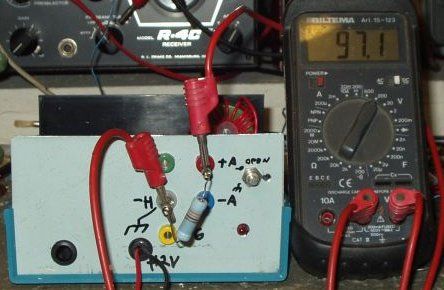
The DC/DC-inverter under test
You may wish to see the originator's comments about the dc-dc inverter
Suggested mains power supply for Kw.E.a, Lw.E.a,
Fu.H.E.c, Torn.E.b etc.
Apart from the problem of finding a suitable box to house
the power supply unit......, the worst problem is to find a
suitable transformer without paying too much, but many
transformers are found as surplus. So if you start with a
transformer to say, 14V and buy one to transform back to 100-120V
for the anode supply, then LA6NCA's inverter will solve the
heater problem. It may also provide an additional negative bias
voltage of 0...-10V. The original supply is discontinued because
we have some interference problems to solve, but do not
experience such problem with the half part which delivers
filament voltage.
See Norwegian language articles about mains power supply units
for these receivers on page e96
Got some interesting data sheets from Hans Jürgen Keller /
DH1AB; Thomson (ST) VB408 high voltage regulator
which may be used in series regulator from +1.5....370V 40mA
output (max input +400V), 89W max power for the TO220 version. It
should be quite suitable
for most Wehrmacht receivers.
Suggested values for 90V output. D=1N4004, R1= 1kW, R2= 68kW, C1=
1µF, C2= 10µF 150V, estimate 120-150VDC input. 130V output for
R2=100kW, with respectively higher
input voltage.
Another idea for making supplies from +12V is found in TNC2 or
MFJ1270/1270B, it uses an NE556 type dual monoflop device to
produce a dual phase signal which is rectified in a two-way
bridge, or fed to an amplifier stage. Note that 1N4001 or 4002
works, I've tested it on 10 and 20kHz switch frequencies and
couldn't see any problems with output current up to 50mA
Regulated mains power supply for Luftwaffe
receivers (EZ6, E10L, E10K)
Power supply for
EZ6, E10K, E10L and similar Luftwaffe receivers
EZ6, EL10, and EK10 require 25.2VDC and +210VDC. Perhaps
not too critical. They will work with 12.6V heater - without any
hum problems, but the motor in EZ6 will of course not operate
with AC supply. It isn't really neccessary to use stabilized
anode supply, but the problem is to find suitable mains
transformers,
so I decided to use a regulator. Have already built supplies with
EL86 type shunt regulators, but with the available components it
seems better idea to use a series regulator. LA4OE runs his EZ-6
with 150V supply voltage and it still works fine.With +200V
supply EZ6 draws 38-40mA anode current, 2mA more with BFO, but
less for strong signals.
EZ6 motor supply isn't solved, and I haven't investigated into
running it, it might operate with a simple rectifier to +24V, but
it is only a cosmetic problem - as long as you don't have any of
the DF antenna system to go with it, you have no need for
installing the motor.
Considered some different regulators. A valve is better if the
voltage drop over the regulator is large, but today you can
always find some mosfets to use. Problem with high voltage BJT's
is that they have very low current gain, and only few have in the
region of HFE=10 (except MJE340), so you need to make a
darlington circuit. I will eventually build such regulator later,
but this was made 8 years ago dependent on available components.
Philips EL86 has proven to be a very useful valve since it will
draw 100mA triode connected with only 100V, it is difficult to
find another valve to do the same, with similar size and heater
current. Other valves requires higher screen voltage, but this is
always a problem when limited supply voltages are available..
In my construction the voltage from the rectifier varies between
250-290V, it means that the regulator have minimum 40V across it,
and maximum 80v. So unless you don't shortcuit the output it is
no real danger with a 100V device, you may also use a zener diode
across it to protect it.
I used a Radio Spare device which stands at least 200V, but I
have no data.
Another problem with shortcircuit is that the small transistors
Q3, 4, 5 are very likely to have secondary breakdown. Even the
old type 2N398 will work satisfactorily. The 1k resistor in
series protects against such, and it is always better to cascade
lower voltage devices instead of using for a 300V type. I have
lots of suitable HV-devices, but find it more interesting to
prove that low cost devices will work just as good provided you
take proper steps.
It is very important for valves to have soft start in heater
supply, it may increase the life-time a lot, so I still hope to
have the over 60 years old valves for many years. The relay was
measured and operated with the current shown. You just look for a
higher voltage relay and make some tests to find the optimum
relay (which draw as little current as possible, often AC relays
will give best results in such respect).
In order to avoid damages if output is shortcircuited a smaller
value resistor is inserted in series with the fuse, it will slow
down the transient so the fuse have time to blow before the power
supply.
See more notes about these receivers on page
23a
Power supply for Ukw.E.e/Ukw.E.h
(+120...130V 30mA, and 12,6VAC 2A)
Netzgerät für Ukw.E.e/Ukw.E.h
(+120...130V 30mA, and 12,6V 2A)
 |
 |
Got a power supply with the UkwEe many years ago,
and when I opened it it was quite a surprise that nothing had
been shortcircuited, and another surprise was that the 120V DC
was 210V which is quite a lot for this kind of receiver. It is
always a problem to find boxes so I decided to keep this ugly box
- even the selenium rectifiers since they seem to work properly,
but I needed a regulator to drop the voltage. It is an advantage
with cardboard or wooden boxes, but it was really not much space
inside. The best solution seems to mount the voltage regulator on
the back. Wanted some VB408, but it would take time, so I decided
to try the insulated type BUT12AF which don't need any mica dish
and one avoids the problem to consider if the mica is good enough
for the voltage.
Since many of the UkwEe's have bad paper capacitors which may
shortcircuit, a current protection seems to important. It is set
to 40mA. In spite that the power may not exceed 1W a large
cooling fin was put on the rear, for practical reasons this is -A
plane which means it may swing to -3V and as such is not a
problem (see explanation further down the page). It Is a a
problem with BUT12AF or BU508 that the HFE is rather low, only
10. This was measured before starting the construction. Probably
would an MJE340 be better in this respect, but again it needs
mica dish with the problem of flash-over to ground. Zener diodes
were taken from what was available to make an output voltage
around 130V and stand 5mA current. Since zener diodes are quite
noisy a 0,47µF decoupling capacitor is connected across them,
but to avoid peak current in the base circuit if the output is
shortcircuited a diode gate is used toward the gate. Voltage
regulation is not important for this type of regulator, and UkwEe
receiver has its own 95V neon type regulator for the local
oscillator. The voltage drop resistors were calculated to have
the minimum current neccessary, and still not burn with
shortcircuited output. Although not planned, all components could
be mounted on the rear late, with a square hole so the power
transistor could be screwed to the cooling plate - remember
thermal compound.
Used pieces of pcb laminate to support the construction - for
soldering points - with at least one screw and araldite glue.
A more ideal power supply for checking the state
of old receivers.
Having built the unit shown above I soon discovered how it would
ideally have been. As already mentioned the paper capacitors are
likely to be shortcircuited, and in the next receiver to be
tested two capacitors were shorted, one for +130V supply voltage
and another for audio amplifier screen voltage. If a 40mA lamp is
connected in series with the power transistor it would light up
when current approaches this value, and for normal current which
should be 30mA it will only glow. The lamp voltage is not
important. But this was not the only short, the on/off switch was
wired incorrect, shorting the heater supply, and the transformer
got very hot. I didn't find the fault before I connected another
12VDC supply with a 10ohm series resistor. Such shortcircuit
indication could have been done with a smaller car lamp switched
in series with the heater voltage.
Considerations for using the same power supply connection/cable with different equipment (note the different heater current).
 Torn.E.b +2V 0,8A +90V 10mA |
 KwEa: +2V 2,2A ..+90V 20...25mA LwEa: +2V 1,8A .......+90V 20mA |
FuHEc: +90V..20mA +2V... 1,9A |
 +2V 1,14 / 2,25A +135V 20...25/30...45mA -G: -4,5V (Sollwert) |
 +2V 0,89 / 1,14A +135V 25 / 40mA -G = -4,5V ? |
FuHEu: +90V...19mA +2V..1,8A |
Some silicon diodes are added (modification) for Torn.Fu.d2
(unfortunately not equal to Torn.Fu.b1 / c / f.
It was considered some different use of pin 3 on the power
supply. When it is called +Umf it is supposed to
switch a relay or other in the power supply when the receiver is
in use, see figure. I am not sure if I should have seen such
application mentioned. It may still bet available, but if a diode
is added, the same pin 3 can be used for negative voltage
Torn.Fu.d2 without causing any damage when different units are
connected using the same power supply and cables. When it is used
for negative voltage it is no current consumption, so it can be
kept relatively high impedanced, say 1000W
or higher, and and the circuit requiring positive voltage from
the equipment may use an isolating diode. The returned voltage
from KwEa, LwEa and other are reduced to 1,3V, and it may be
difficult to find a suitable relay, so a transistor may be added
to switch a relay, but now one may use +8V from the low voltage
rectifier.
For NA6 the anode voltage is limited to 90...100V, but it is not
so bad, the transmitters will still work. See also notes for
NA6/NA6a on page 28c . For
LA6NCA's power supplies this is no problem, it is possible to
achieve stabilized voltage up to +200V with his new circuit.
Some more power requirement for equipment:
Lo1UK35 (SE 42444/c):
Empfang .........+2V 1,3A, 130V 40mA, -3V Sollwert
Telefonie: ....... +2V 1,7A, 130V 50mA, -3V
Telegr. tönend: +2V 1,7A, 130V 50mA, -3V
Telegr. tonlos:. +2V 1,7A, 130V 60mA, -3V
E381S (E381H) power requirements:
+3,8V 0,35A
100V 20mA
-1,5V zero current
-3V zero current
The power supply mentioned above is suitable for this receiver
(since filament voltage may be adjusted up towards +12V).
The same cables will also work for Ukw.E.e and
Ukw.E.h and other equipment.
See list of mains adapters for possible used to transform back from LT to HT supply voltage on page p31
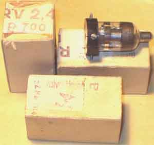
Some RV2,4P700 just bought from the local surplus shop.
Socket connections. Note that suppressor
grid for RV2P800 is not connected to the filament inside the
glass tube, but inside the socket/tube, so it is possible -
according to SM6HYG Carl-Gustaf to reconnect it to a free pin on
the socket, suppose the same applies for RV12P4000 (?).
| German power connectors | |
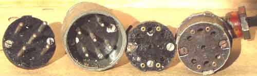 |
Male and female type Wehrmacht-connectors for +90 (+130V), +2 (12V) and -3V |
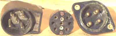 |
1) Another type Wehrmacht cable connector 2) Wehrmach connector with larger holes 3) AC mains power connector for Lo6K39, Lo6L39 |
Back to index for German receivers (pg11a)
Last update: 2003-06-14